Radiation process and apparatus

a radiation treatment and process technology, applied in the field of radiation treatment system and method, can solve the problems of difficult to achieve accurate control of the amount, location and distribution of radiation within the patient's body, and achieve the effect of minimizing the radiation exposure of the surrounding region and optimal quality radiation therapy

Active Publication Date: 2007-10-30
VARIAN MEDICAL SYSTEMS
View PDF21 Cites 87 Cited by
  • Summary
  • Abstract
  • Description
  • Claims
  • Application Information

AI Technical Summary

Benefits of technology

The present invention provides an apparatus and method for performing optimal quality radiation therapy. It accurately dosages target regions while minimizing radiation exposure of surrounding regions. The quality of the radiation therapy is not significantly affected by improper patient positioning, patient movement, patient condition changes, or inadequately optimized planning.

Problems solved by technology

The technical problem addressed in this patent is the difficulty in achieving accurate control of radiation treatment due to factors such as movement in the patient's body, changes in organ structure or composition, and changes in the relative position of organs. The invention aims to provide an apparatus and method for radiation therapy that can minimize radiation exposure to healthy regions and ensure consistently high quality of the treatment.

Method used


Image

  • Radiation process and apparatus
  • Radiation process and apparatus
  • Radiation process and apparatus

Examples


Embodiment Construction

[0018]Various embodiments of the present invention are described hereinafter with reference to the figures. It should be noted that the figures are not drawn to scale and elements of similar structures or functions are represented by like reference numerals throughout the figures. It should also be noted that the figures are only intended to facilitate the description of specific embodiments of the invention. They are not intended as an exhaustive description of the invention or as a limitation on the scope of the invention. In addition, an illustrated embodiment needs not have all the aspects or advantages of the invention shown. An aspect or an advantage described in conjunction with a particular embodiment of the present invention is not necessarily limited to that embodiment and can be practiced in any other embodiments of the present invention even if not so illustrated.

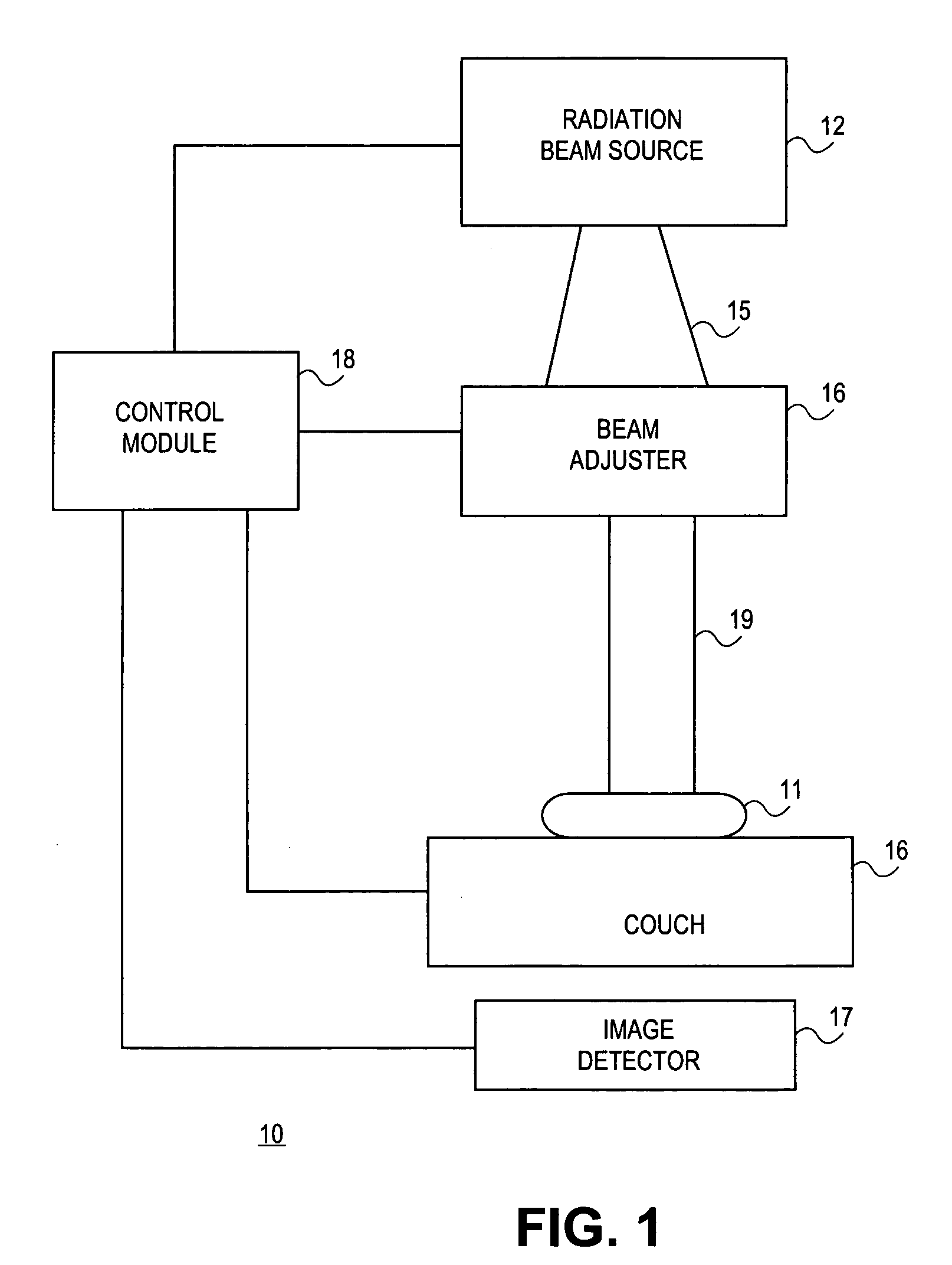
[0019]FIG. 1 is a functional block diagram illustrating a radiation treatment apparatus 10 in accordance with...


PUM


Abstract

A radiation apparatus (10) includes a beam source (12) generating radiation beam toward a target (11). A projection detector (17) detects the images of the target (11) formed by the radiation beam. In a radiation treatment session using the apparatus (10), the beam source (12) first generates a low intensity beam. The projection detector (17) generates image signals of a patient under the treatment. A control module (18) in the apparatus (10) develops a treatment plan in accordance with a treatment prescription and the image signals. Subsequently, the beam source (12) generates a treatment beam according to the treatment plan. The projection detector (17) can generate further image signals formed by the treatment beam to verify the treatment process.

Description


Claims


Application Information

Patent Timeline
Owner VARIAN MEDICAL SYSTEMS
Why Eureka
Try Eureka