Apparatus and method for changing printing sleeves on a printing machine

a printing machine and printing sleeves technology, applied in the field of apparatus and method for changing printing sleeves on printing machines, can solve the problems of long production down time of printing machines, mounting and/or demounting printing sleeves directly on the impression cylinder and consequently within the printing machine, and achieve the effect of facilitating pushing

Inactive Publication Date: 2007-11-06
MANROLANAD AG
View PDF19 Cites 17 Cited by
  • Summary
  • Abstract
  • Description
  • Claims
  • Application Information

AI Technical Summary

Benefits of technology

[0006]The apparatus according to the invention serves for the mounting and / or demounting of at least two printing sleeves outside a printing unit of a printing machine. In particular, the apparatus of the present invention permits the mounting and / or demounting of an outer printing sleeve forming a printing surface, a blanket sleeve or of an inner printing sleeve providing diameter compensation between the outer printing sleeve and an impression cylinder of the printing machine. The apparatus according to the invention including at least the following subassemblies: a) a reception device onto which an inner printing sleeve can be pushed for the mounting of the two printing sleeves; and b) at least one compressed-air device for helping to fix the inner printing sleeve on the reception device and for conducting compressed air through orifices assigned to the inner printing sleeve for the mounting of the two printing sleeves. The latter compressed-air device thereby allows for an outer printing sleeve to be pushed more easily onto the inner printing sleeve.

Problems solved by technology

Furthermore, carrying out the mounting work and / or demounting work directly on the impression cylinder and consequently within the printing machine may lead to long production down time of the printing machine.
The mounting and / or demounting of the printing sleeves directly on the impression cylinder and consequently within the printing machine is therefore generally a disadvantage.

Method used


Image

  • Apparatus and method for changing printing sleeves on a printing machine
  • Apparatus and method for changing printing sleeves on a printing machine
  • Apparatus and method for changing printing sleeves on a printing machine

Examples


Embodiment Construction

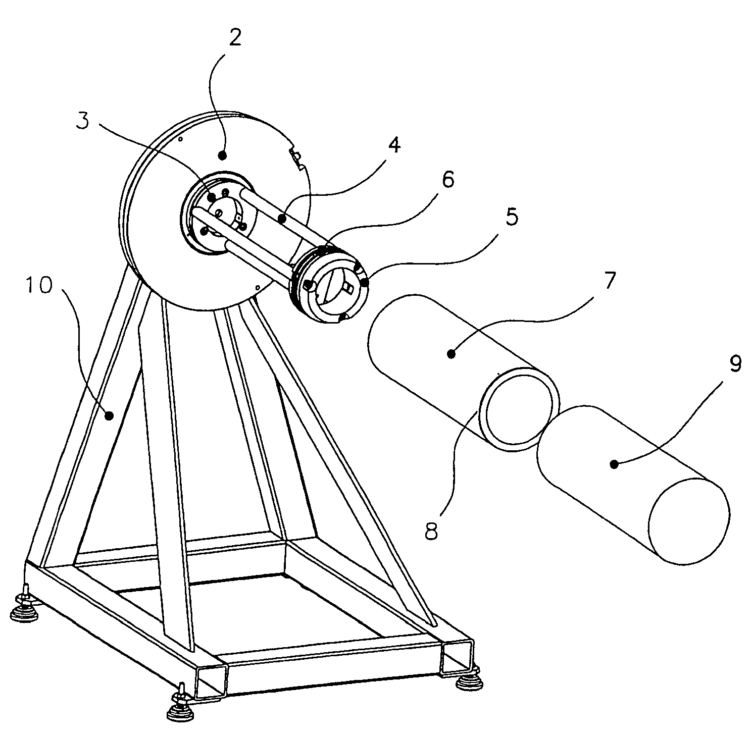
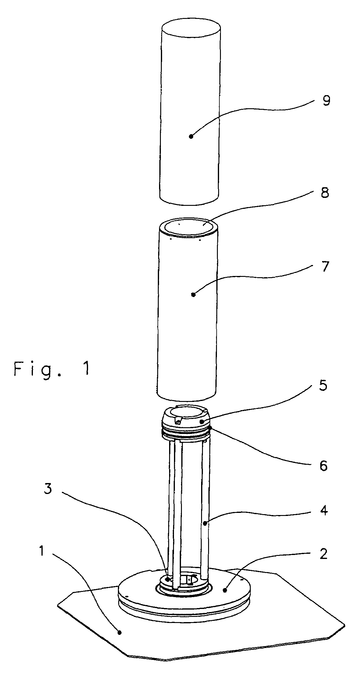
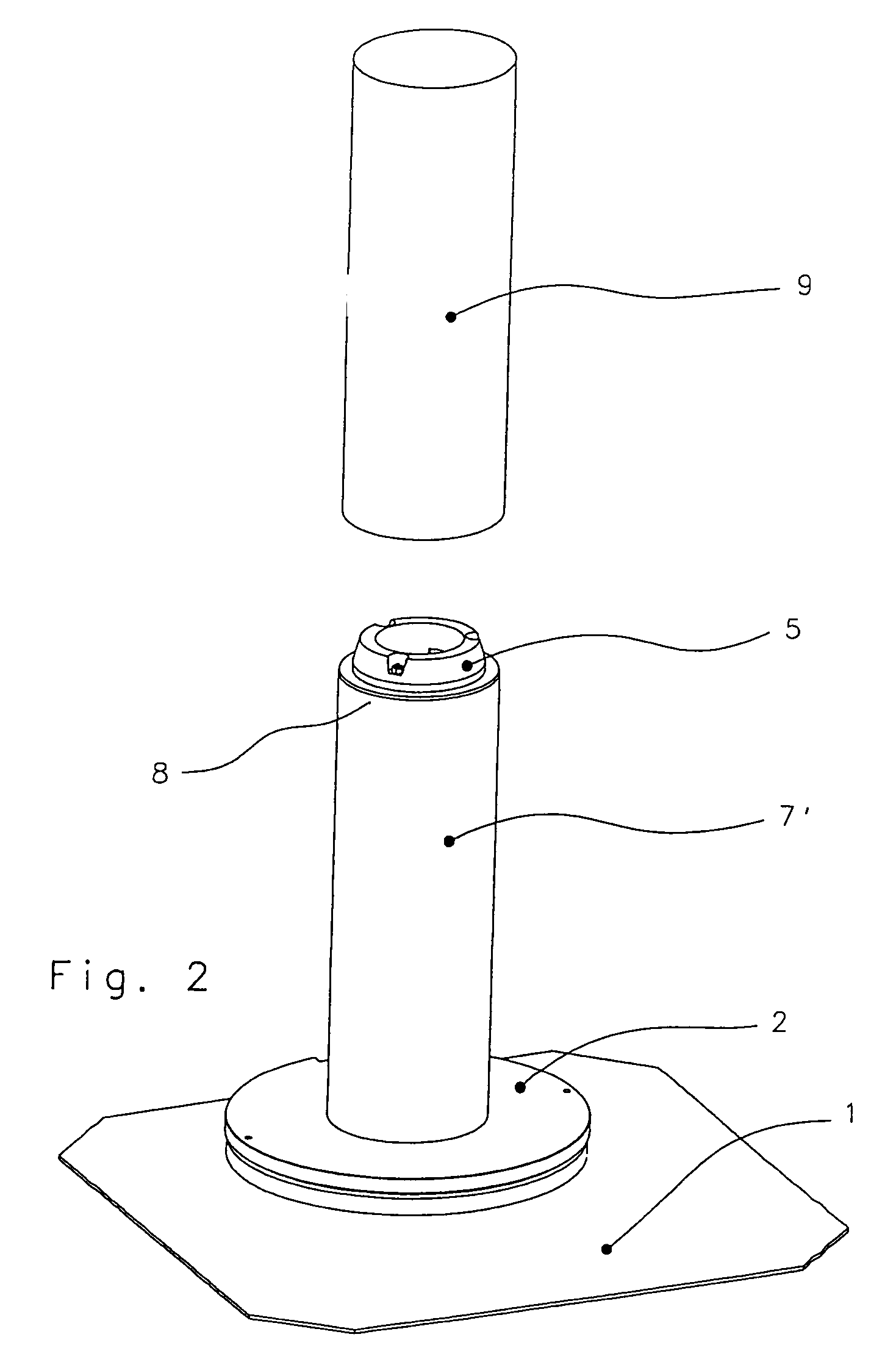
[0013]The present invention is described in greater detail below with reference to FIGS. 1 to 6. FIGS. 1 to 6 show three different exemplary embodiments of an apparatus according to the invention for the mounting and / or demounting of two printing sleeves outside a printing unit of a printing machine. In particular, the apparatus can be used for the mounting and / or demounting of an outer printing sleeve and of an inner printing sleeve. In such a case, the outer printing sleeve forms a printing surface and the inner printing sleeve provides diameter compensation between the outer printing sleeve and an impression cylinder of a printing machine.

[0014]A first exemplary embodiment of the apparatus according to the invention is shown in FIGS. 1 and 2. In the embodiment of FIGS. 1 and 2, the apparatus according to the invention is mounted on a baseplate 1 that extends essentially in a horizontal direction. The apparatus includes a reception device that is mounted on a plate forming a stop ...


PUM


Abstract

The invention provides an apparatus for the mounting and / or demounting of at least two printing sleeves outside a printing unit of a printing machine. The printing sleeves include an outer printing sleeve forming a printing surface and an inner printing sleeve providing diameter compensation between the outer printing sleeve and an impression cylinder of the printing machine. The apparatus having a reception device onto which an inner printing sleeve can be pushed for mounting the two printing sleeves. The apparatus having at least one compressed-air device for facilitating the fixing of the inner printing sleeve on the reception device and for conducting compressed air through orifices assigned to the inner printing sleeve in order thereby to make it possible for an outer printing sleeve to be pushed more easily onto the inner printing sleeve.

Description

FIELD OF THE INVENTION[0001]The present invention relates to an apparatus for mounting and / or removal of a plurality of printing sleeves on a printing machine. The invention also relates to a method for changing printing sleeves on a printing machine.BACKGROUND OF THE INVENTION[0002]In printing operations, a current practice is to position what may be referred to as printing sleeves on impression cylinders of a printing machine. Such printing sleeves allow a smooth and jolt-free rolling of the cylinders of a printing machine that are involved in printing. Where printing machines of variable format are concerned, two printing sleeves are positioned one above the other on the impression cylinders. An outer printing sleeve forms a printing surface, and an inner printing sleeve serves for diameter compensation between the outer printing sleeve and the respective impression cylinder of the printing machine. In such cases, the outer printing sleeve usually has a small wall thickness, wher...

Claims


Application Information

Patent Timeline
Patent Type & Authority Patents(United States)
IPC IPC(8): B41F13/00B41F13/34B41F27/06B41F13/10B41F13/24B41F27/00B41F27/10B41F27/12B41F30/00
CPCB41F27/105B41P2227/60
Inventor PETERSEN, GODBERGOTTLING, JOSEFHARTMANN, THOMAS
Owner MANROLANAD AG
Why Eureka
Try Eureka