Power unit structure for hybrid vehicle

a technology of hybrid vehicles and power units, applied in electric propulsion mounting, bicycles, transportation and packaging, etc., can solve the problems of increased motor size, increased rated output, and difficulty in ensuring a sufficient reduction ratio from the motor to the drive wheel, etc., to achieve the effect of increasing the size of the motor

Inactive Publication Date: 2007-11-06
HONDA MOTOR CO LTD
View PDF15 Cites 12 Cited by
  • Summary
  • Abstract
  • Description
  • Claims
  • Application Information

AI Technical Summary

Benefits of technology

[0011]The present invention has been conceived in view of the above-described problems, and an object of the present invention is to provide a desired shaft torque to a drive wheel without increasing the number of parts or increasing the size of a motor.
[0012]In order to solve the above described problems, an aspect of the present invention is directed to a power unit structure for a hybrid vehicle, provided with an engine (for example, an engine 20 in an embodiment that will be described later), power transmission means (for example, a continuously variable transmission 23 in an embodiment that will be described later) for transmitting rotational force of a crankshaft (for example, a crankshaft 22 in an embodiment that will be described later) connected to the engine to a drive wheel (for example, a rear wheel WR in an embodiment that will be described later) side, a driven shaft (for example, a driven shaft 60 connected to the rear wheel WR via a reduction gear mechanism 69 in an embodiment that will be described later) connected to a driven side of the power transmission means, a reduction gear mechanism (for example, a reduction gear mechanism 69 in an embodiment that will be described later) for reducing rotational force of the driven shaft and transmitting to the drive wheel, and a motor (for example, a drive motor 21b in an embodiment that will be described later) for transmitting power to the drive wheel, wherein the motor is attached to the reduction gear mechanism.
[0013]According to this type of structure, it is possible to reduce and transmit power from the motor to the drive wheel using the reduction gear mechanism provided between the power transmission means and the drive wheel.

Problems solved by technology

In addition, with the above-described configuration where the motor is directly connected to the driven shaft of the power transmission means, it is difficult to ensure a sufficient reduction ratio from the motor to the drive wheel.
Therefore, there is a problem in that the motor is increased in size.
Therefore, a rated output normally becomes large, and the amount of heat generated also becomes large.
However, the vehicle disclosed in the above-described patent document is normally a motorcycle, and not a hybrid vehicle where engine power and motor power are combined and transmitted to the drive wheel side.

Method used


Image

  • Power unit structure for hybrid vehicle
  • Power unit structure for hybrid vehicle
  • Power unit structure for hybrid vehicle

Examples


Embodiment Construction

[0045]An embodiment of the present invention will now we described with reference to the accompanying drawings, wherein the same or similar elements have been identified by the same reference numeral throughout the several views. In the following description, front side refers to the advancing direction of the vehicle, and right side and left side refer to the right side and the left side facing in the advancing direction of the vehicle.

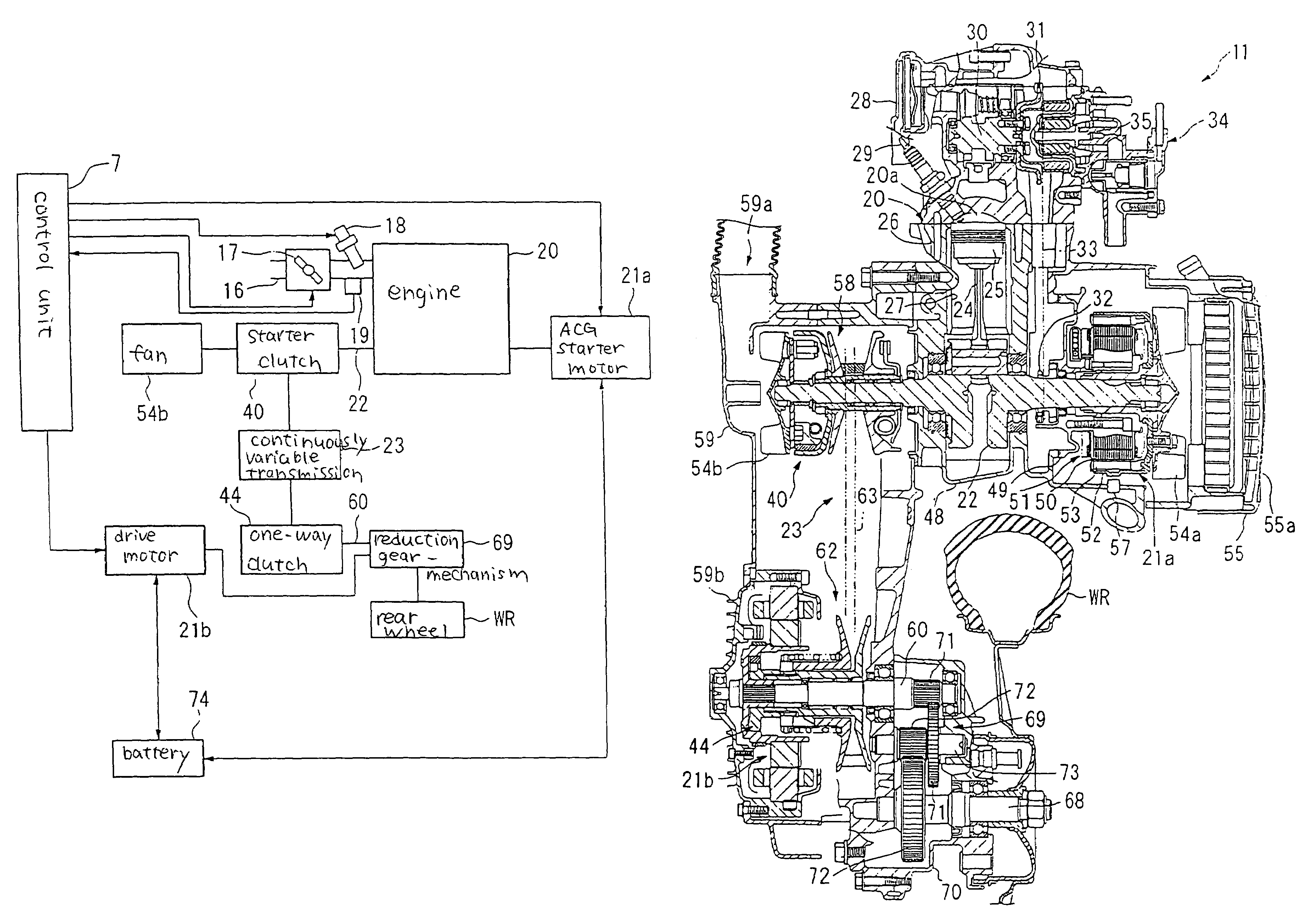
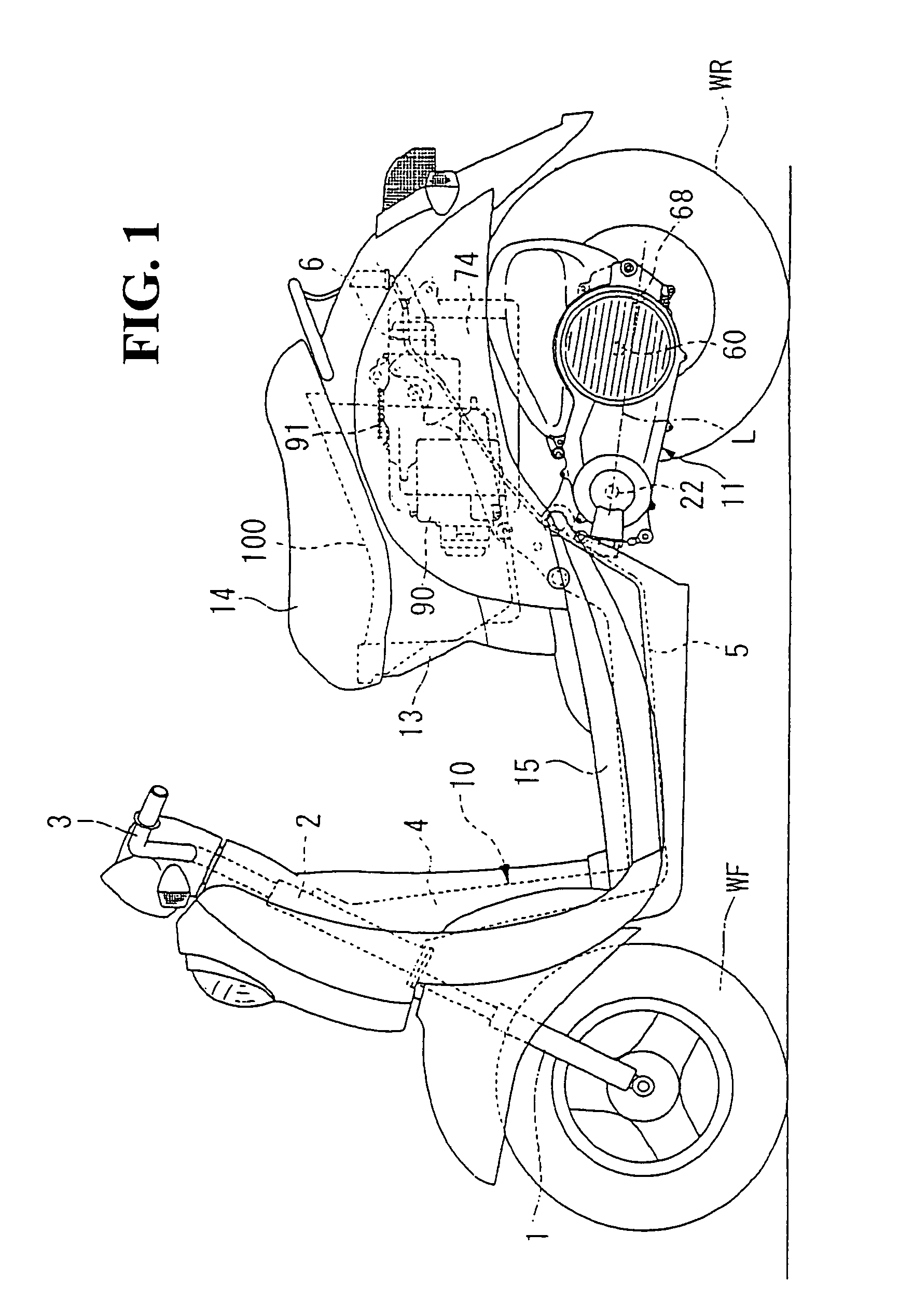
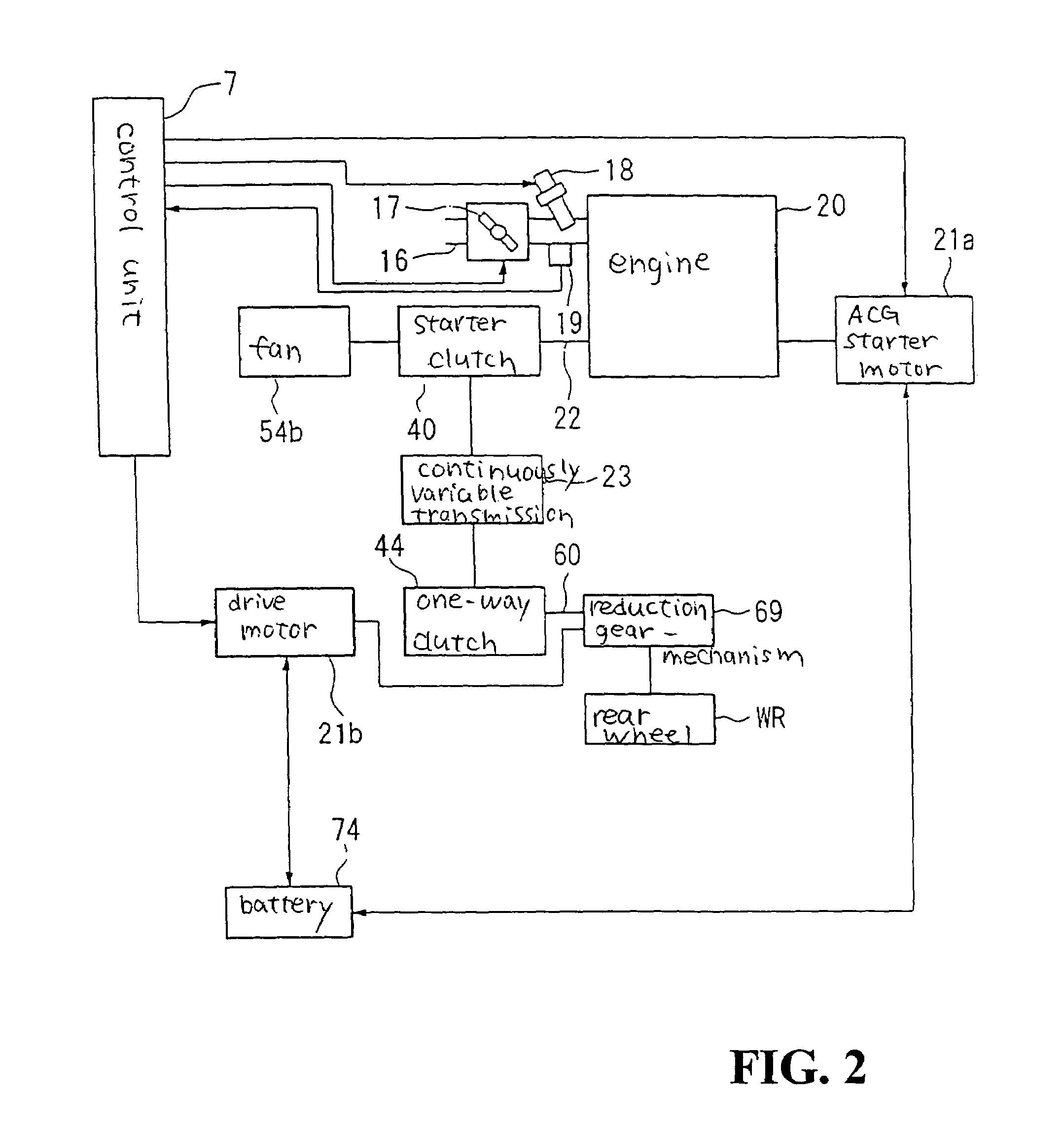
[0046]As shown in FIG. 1, a hybrid vehicle according to an embodiment of the present invention is a unit swing type two-wheeled vehicle, having a front fork 1 where a front wheel WF is axially supported at the front of the vehicle. The front fork 1 is pivoted on a head pipe 2, and can be steered by operating a handle 3. A downpipe 4 running to the rear and down is attached from the head pipe 2. A middle frame 5 extends substantially horizontally from a lower end of the down pipe 4. Furthermore, a rear frame 6 is formed running rearwards and upwards f...


PUM


Abstract

To provide desired shaft torque to a drive wheel without increasing the number of parts or increasing the size of a motor, to improve cooling capability of a generator housed inside a transmission case, and to improve energy transmission efficiency and electrical generation efficiency in an engine unit of a hybrid vehicle. A power unit structure for a hybrid vehicle is provided with an engine, a continuously variable transmission, a driven shaft, a drive motor and a reduction gear mechanism. The drive motor is attached to the reduction gear mechanism.

Description

CROSS-REFERENCE TO RELATED APPLICATIONS[0001]This nonprovisional application is related to Japanese Patent Application Nos. 2003-338823, 2003-338824 and 2003-338825, each filed on Sep. 29, 2003. The entirety of each of the above documents is incorporated herein by reference.BACKGROUND OF THE INVENTION[0002]1. Field of the Invention:[0003]The present invention relates to a power unit structure for a hybrid vehicle, having an engine and a motor as drive power sources.[0004]2. Description of Background Art:[0005]In the background art, a known hybrid vehicle has power transmission means for transmitting power from an engine to a drive wheel housed inside a transmission case. The power transmission means combines and transmits power from the engine and power from a motor to a drive shaft (see, for example, Japanese patent laid-open No. Hei. 8-175473). The hybrid vehicle disclosed in the above document has a generator connected directly or though a reduction gear to a driven shaft of the ...

Claims


Application Information

Patent Timeline
Patent Type & Authority Patents(United States)
IPC IPC(8): B60K6/00B60K1/02B60K6/40B60K6/48B60K6/543
CPCB60K6/40B60K6/48B60K6/543B60K1/02Y10S903/912B60Y2200/126B62K2202/00Y02T10/6221Y10S903/951B60Y2200/12Y02T10/62
Inventor OZEKI, TAKASHITSUKADA, YOSHIAKIINOMOTO, YUTAKASHIBATA, KAZUMI
Owner HONDA MOTOR CO LTD
Why Eureka
Try Eureka