Optical fiber holding apparatus and optical fiber fusion-splicing apparatus including the same

a technology of optical fiber fusion and holding apparatus, which is applied in the direction of optics, optical light guides, instruments, etc., can solve the problems of reducing the press force of the fiber clamp for holding the inability to obtain satisfactory holding force of the coated optical fiber, and the inability to meet the requirements of the electrode rod, etc., to achieve small distance and reduce interference with other components

Active Publication Date: 2007-11-06
SUMITOMO ELECTRIC IND LTD
View PDF11 Cites 8 Cited by
  • Summary
  • Abstract
  • Description
  • Claims
  • Application Information

AI Technical Summary

Benefits of technology

[0012]As described above, the elastic member for imparting a force for pressing the optical fiber onto the stage (fiber holding force) to the fiber holding section is provided in a portion not immediately above the fiber holding section but at a position away from the fiber holding section (at the one end side of the arm fixed in a rotatable state). Accordingly, since a part of the lid section does not have to be disposed immediately above the fiber holding section, a space (buffering space for reducing interference with other components) is ensured immediately above the fiber holding section. Therefore, for example, when the optical fiber holding apparatus according to the present invention is mounted on an optical fiber fusion-splicing apparatus, in view of miniaturization of the optical fiber fusion-splicing apparatus, the optical fiber holding apparatus and other components such as the electrode rod-supporting base can be disposed with an extremely small distance. Under such circumstances, the structure of the optical fiber holding apparatus can prevent the lid section from interfering with other components while the lid section is opened / closed.
[0014]In the optical fiber holding apparatus according to the present invention, the arm has such a shape that, when the lid section and the stage are in the state of the first posture, the portion excluding the other end provided with the fiber holding section is shaped from the loading plane of the stage. This arrangement is particularly effective when holding a loose tube fiber the optical fiber of which is received within a tube having a predetermined diameter. That is, the arm has such a shape that, when the fiber holding section holds the front-end portion of the optical fiber onto the stage in a state that the loose tube fiber, which has the front end portion of the optical fiber exposed from the tube, is loaded on the loading plane of the stage, a space is formed between the tube and the fiber holding section. In such a structure that, in a state that the fiber holding section holds the front end portion of the optical fiber onto the stage and the arm comes into contact with the tube, for example, when the tube is hard to be deformed, the arm is prevented from being pushed out by the tube itself, and accordingly satisfactory force of the fiber holding section to press the optical fiber may not obtained. However, in the above-described arrangement of the optical fiber holding apparatus, the fiber holding section holds the front-end portion of the optical fiber exposed from the tube onto the stage without abutting on the tube. Therefore, even when the tube is hard to be deformed, the front-end portion of the optical fiber can be held by the fiber holding section with a satisfactory force.
[0015]In the optical fiber holding apparatus according to the present invention, the fiber holding section, which is provided at the other end of the arm, preferably includes a cushioning member provided on the surface, which faces the loading plane of the stage in the first posture. In this case, owing to such arrangement, even when the fiber holding section holds the front-end portion of the optical fiber, the optical fiber itself is effectively prevented from being damaged.
[0016]Furthermore, the optical fiber fusion-splicing apparatus according to the present invention has a structure for fusion-splicing optical fibers, the end faces of which are butted against each other. In particular, a pair of optical fiber holding apparatuses (first and second optical fiber holding apparatuses) each having the above-described structure and a discharge means are provided. The first and second optical fiber holding apparatuses are disposed on a predetermined installation surfaces so that the directions of the front-end portions of the loaded optical fibers coincide with each other. The discharge means discharges into the space sandwiched between the first and the second optical fiber holding apparatuses. Owing to the discharge, the end faces of the optical fibers, which are butted against each other, are heated and fusion-splicing between the optical fibers is made possible.
[0017]Particularly, in order to miniaturize the optical fiber fusion-splicing apparatus mounted with the optical fiber holding apparatuses, which have the above-described structure, even when the optical fiber holding apparatuses and other components such as electrode rod supporting bases are disposed with an extremely small distance, the lid sections can be prevented from interfering with other components while the lid sections are opened / closed (change from the first posture to the second posture, or change from the second posture to the first posture). In addition, the biasing force of the elastic member is converged and transmitted onto fiber holding section only, thus a satisfactorily strong holding force can be generated on the optical fibers to be held.

Problems solved by technology

Therefore, in the case where the distance between the optical fiber holding apparatus and the electrode rod supporting base or the like is extremely small, when the clamp chassis is opened and closed to take out the loose tube fiber from the optical fiber holding apparatus after completing the fusion-splicing, the clamp chassis is apt to interfere with the electrode rod supporting base or the like.
In this case, the spring force of the fiber clamp spring cannot be helped from resulting in reduction of the press force of the fiber clamp for holding the coated optical fiber.
As a result, for example, in an optical fiber fusion-splicing apparatus having a proof test function of fiber tensile strength, satisfactory holding force of the coated optical fiber cannot be obtained.
That is, slippage of the coated optical fiber occurs resulting in incorrect tensile test.

Method used


Image

  • Optical fiber holding apparatus and optical fiber fusion-splicing apparatus including the same
  • Optical fiber holding apparatus and optical fiber fusion-splicing apparatus including the same
  • Optical fiber holding apparatus and optical fiber fusion-splicing apparatus including the same

Examples


Embodiment Construction

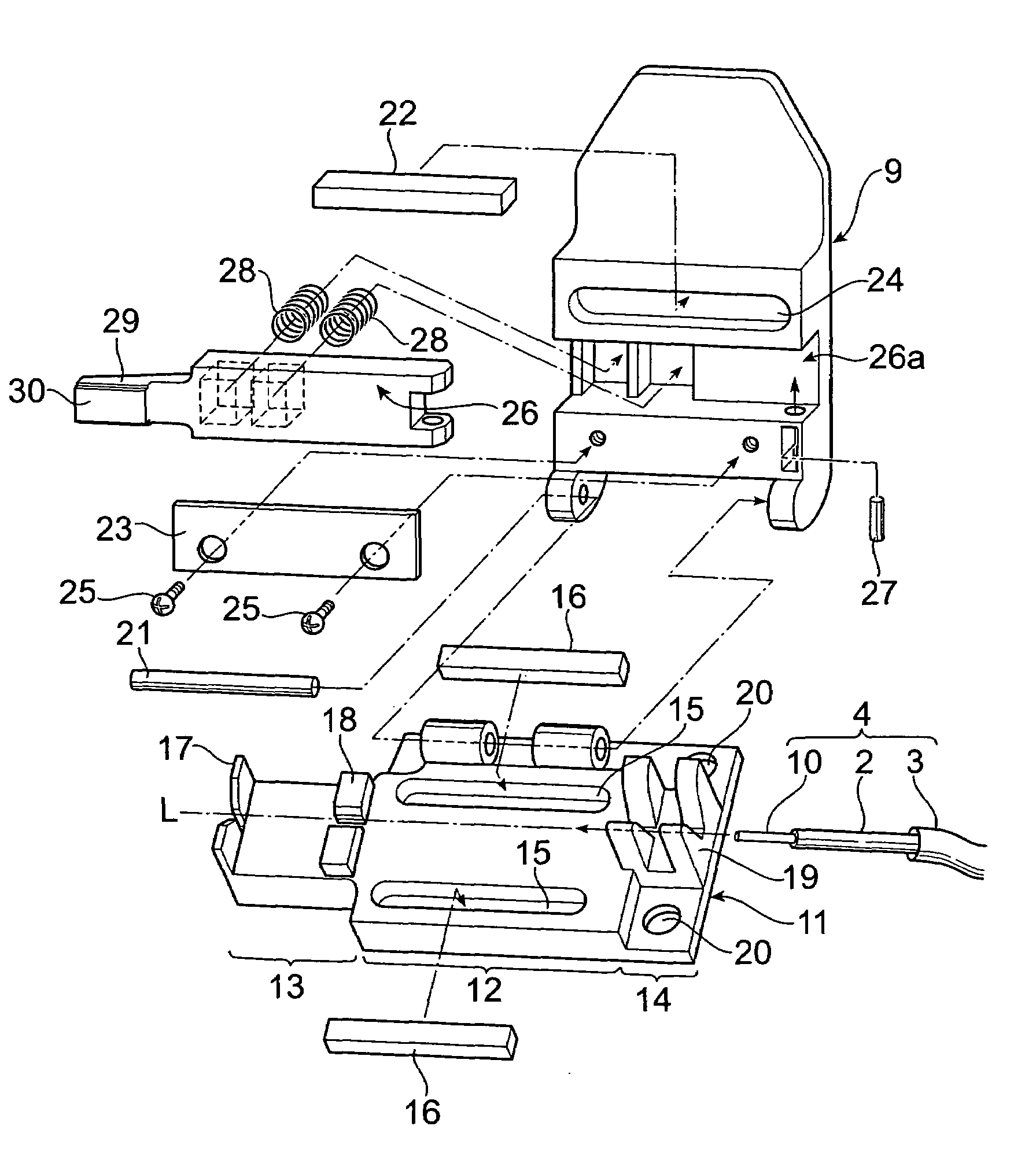
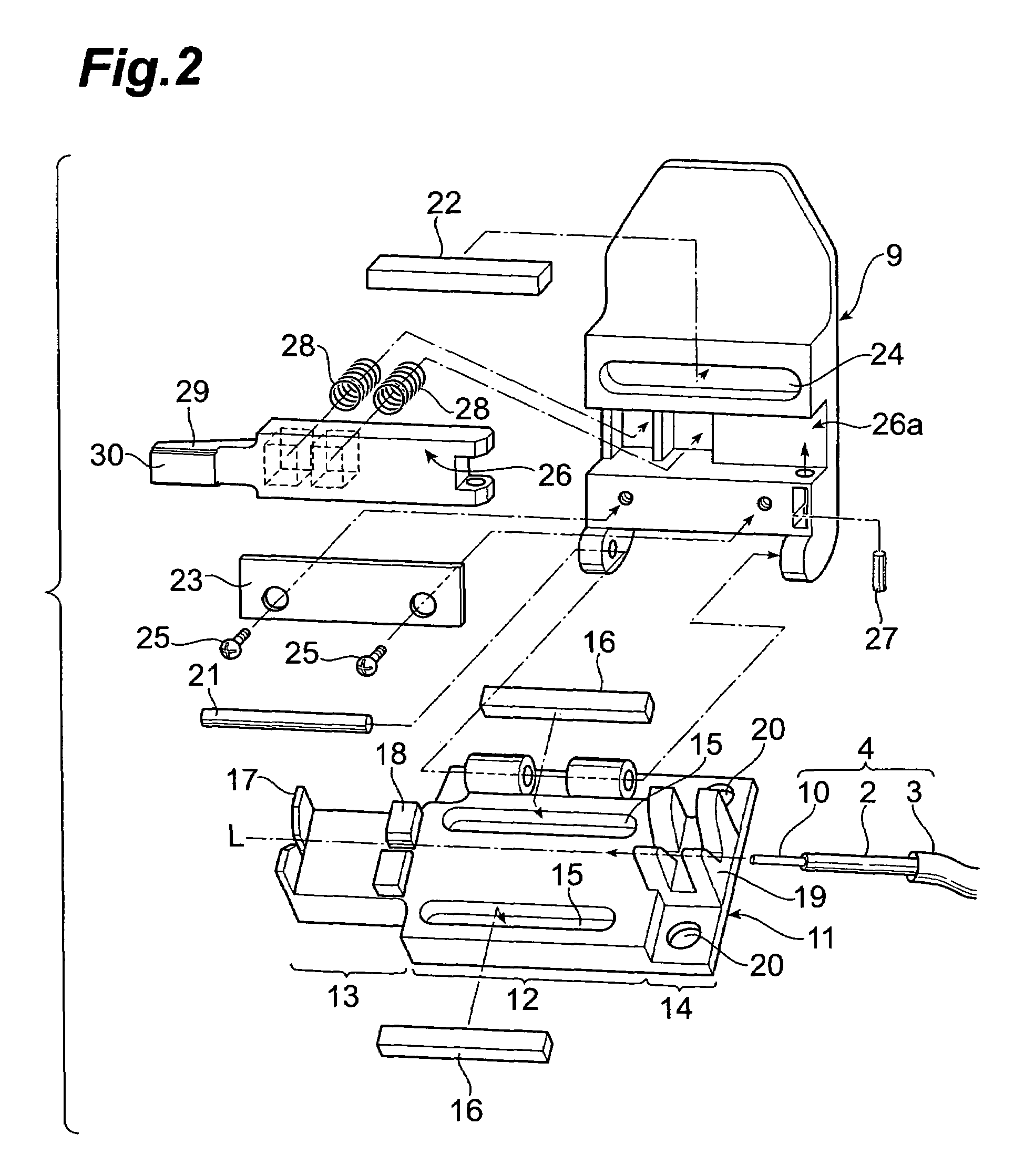
[0027]In the following, embodiments of an optical fiber holding apparatus and an optical fiber fusion-splicing apparatus according to the present invention will be explained in detail with reference to FIGS. 1 to 7. In the description of the drawings, identical or corresponding components are designated by the same reference numerals, and overlapping description is omitted. Also, in the following description, only the optical fiber fusion-splicing apparatus, which connects loose tube fibers by fusion-splicing between the coated optical fibers inserted into tubes, and the optical fiber holding apparatus will be given as typical embodiments.

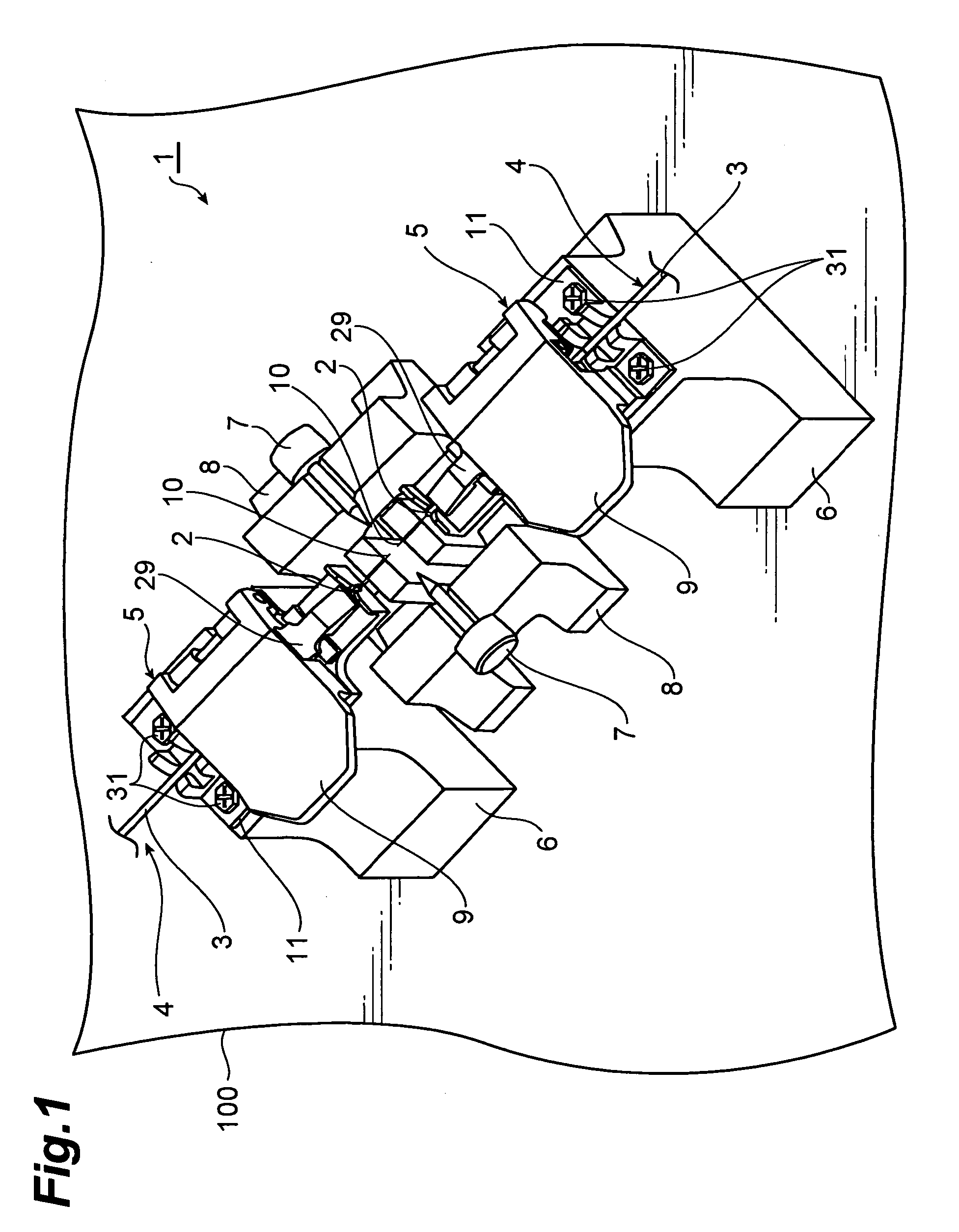
[0028]FIG. 1 is a perspective view schematically showing the structure of an embodiment of the optical fiber fusion-splicing apparatus according to the present invention. The optical fiber fusion-splicing apparatus 1 shown in FIG. 1 is an apparatus that performs fusion-splicing between the coated optical fibers 2, which are inserted into tubes 3 in...


PUM


Abstract

The present invention relates to an optical fiber holding apparatus and the like, which has a structure for stably holding optical fibers with a satisfactory force without interfering with other components even when the apparatus is miniaturized. The optical fiber holding apparatus includes a stage for loading a front-end portion of the optical fiber and a lid section for sandwiching the optical fiber together with the stage. The lid section is rotatably connected with one end of an arm, and a fiber holding section is provided at the other end of the arm. The arm extends along the loading direction of the optical fiber and has such a length that the other end thereof is positioned outside of the lid section. Owing to this arrangement, the optical fiber to be held is pressed onto the stage at a further front-end side than the portion sandwiched by the stage and the lid section. As a result, a buffering space is ensured for avoiding interference with other components between the lid section and the optical fiber end face.

Description

BACKGROUND OF THE INVENTION[0001]1. Field of the Invention[0002]The present invention relates to an optical fiber holding apparatus used for fusion-splicing optical fibers in a state that the respective ends of the optical fibers are butted against each other, and an optical fiber fusion-splicing apparatus including the same.[0003]2. Related Background Art[0004]Some types of optical fiber fusion-splicing apparatus connect, so-called, loose tube fibers each having coated optical fiber inserted into a tube. For example, Japanese Patent Application Laid-Open No. 2001-208931 discloses an optical fiber holding apparatus mounted on an optical fiber fusion-splicing apparatus, which connects loose tube fibers to each other by fusion-splicing the coated optical fibers inserted into a tube. The optical fiber holding apparatus described in the above document comprises a tube clamp, a fiber clamp and a clamp chassis. Here, the tube clamp holds a tube of a loose tube fiber loaded on a chuck stag...

Claims


Application Information

Patent Timeline
Patent Type & Authority Patents(United States)
IPC IPC(8): G02B6/00G02B6/255
CPCG02B6/2551G02B6/3616G02B6/2553
Inventor SATO, RYUICHIRO
Owner SUMITOMO ELECTRIC IND LTD
Why Eureka
Try Eureka