
Method for activating restraining means

a technology of restraint devices and activating means, which is applied in the direction of pedestrian/occupant safety arrangements, instruments, and tractors, etc., can solve the problems of triggering algorithm, more difficult and complex, and restraint device triggering, so as to improve the triggering of restraint devices, improve the reliability of methods, and improve the effect of triggering

Inactive Publication Date: 2007-11-06
ROBERT BOSCH GMBH
View PDF10 Cites 14 Cited by
  • Summary
  • Abstract
  • Description
  • Claims
  • Application Information

AI Technical Summary

Benefits of technology

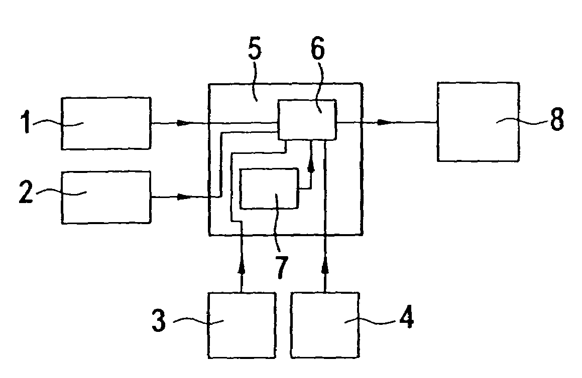
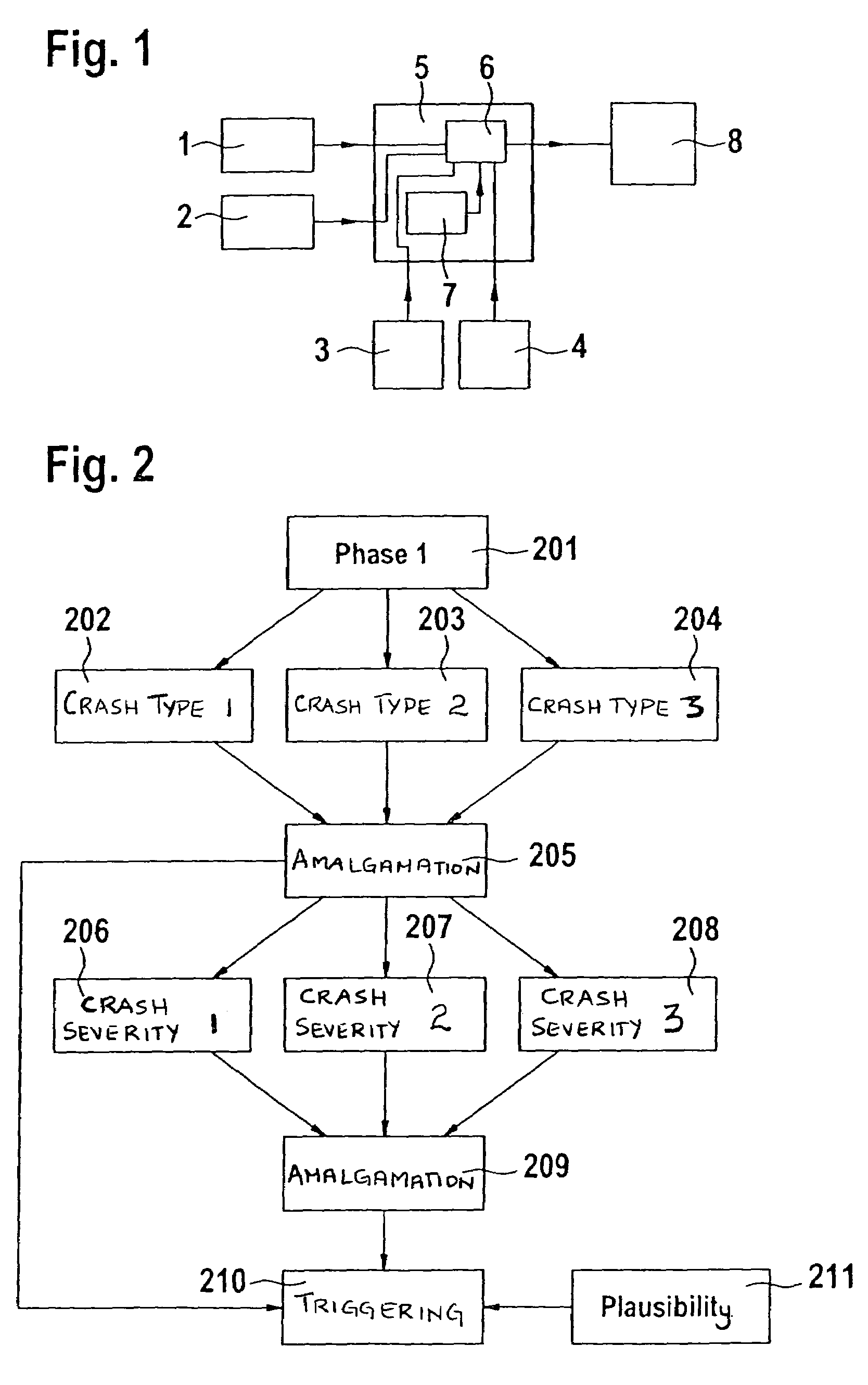
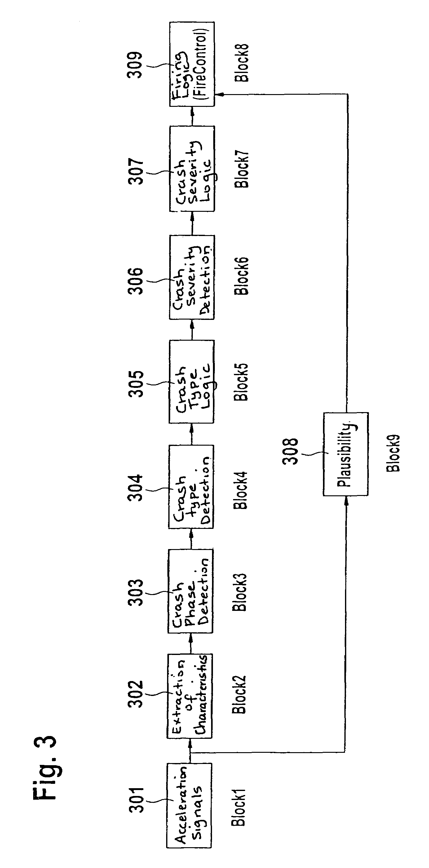
The present invention provides a method for triggering restraint devices in a vehicle in response to a collision detection. The method uses crash phases and crash severity detection to make early decisions regarding triggering. By analyzing signals from sensors in the vehicle and combining them with information about the crash type, the method allows for a more accurate and early triggering of restraint devices. The method is simple and flexible and can be easily expanded with new functions. It also avoids feedback and allows for the combination of different sensor signals to determine the crash type and severity. The method improves safety and efficiency by optimizing the decision-making process in response to collisions.

Problems solved by technology

Thus accidents constituting a powerful event, i.e. a severe accident, may result already early on in the triggering of restraint devices.
Experience shows that the longer a triggering decision or a triggering of restraint devices is deferred, the more difficult and complex will be the triggering algorithm.

Method used


Image

  • Method for activating restraining means
  • Method for activating restraining means
  • Method for activating restraining means

Examples


example

[0054]CRTotal=CRST_⁢1*Fak⁢⁢10+CRST_⁢2*Fak⁢⁢11+…+CRUFS_⁢1*Fak⁢⁢20+CRUFS_⁢1*Fak⁢⁢21+…(Σ⁢⁢Faktoren)CRTotal=CRST_⁢1*Fac⁢⁢10+CRST_⁢2*Fac⁢⁢11+…+CRUFS_⁢1*Fac⁢⁢20+CRUFS_⁢1*Fac⁢⁢21+…(Σ⁢⁢Factors)

[0055]Here, _1 represents the various crash types or crash severities, the prefix indicating the source of the signals.

[0056]As can be seen in FIG. 9, the data from blocks 1.1a through 1.2b are combined in deviation from the basic idea. Block 2 contains the combinations of similar data and block 3 brings these data together to make them available in block 4.


PUM


Abstract

A method for triggering restraint devices in which at least one collision-indicating signal is generated. From the moment that a collision is detected, temporally defined crash phases are specified, and, for every crash phase, a crash type and a crash severity are determined from the signal. The appropriate restraint devices are triggered as a function of the crash severity and / or the crash type.

Description

PRIORITY APPLICATION INFORMATION[0001]This application claims priority to and the benefit of German Patent application no. 102 52 227.8, which was filed in Germany on Nov. 11, 2002, the disclosure of which is hereby incorporated by reference.FIELD OF THE INVENTION[0002]The present invention is based on a method for triggering restraint devices.BACKGROUND INFORMATION[0003]German Patent document no. 199 09 538 A1 refers to a method for triggering restraint devices, in which initially the crash type is determined. If a crash type cannot be inferred unequivocally, probability values are used. The method has a modular structure and features an accident classification module, a calculation module and a comparison module.SUMMARY OF THE INVENTION[0004]By contrast, the exemplary method according to the present invention for triggering restraint devices having the features of the independent claim has the advantage that the crash type and also the crash severity are determined for crash phase...

Claims


Application Information

Patent Timeline
Patent Type & Authority Patents(United States)
IPC IPC(8): B60R22/00B60R21/01B60R21/0132B60R21/0134B60R21/0136B60R21/015
CPCB60R21/013B60R21/01558B60R21/0132B60R21/0136B60R2021/0119B60R21/0134
Inventor SCHULLER, HERMANNLANG, GUNTHERKOLATSCHEK, JOSEFAUST, SABINELICH, THOMASKOEHLER, ARMINMINDNER, KLAUSROELLEKE, MICHAEL
Owner ROBERT BOSCH GMBH
Learn More