Retaining keeper assembly for a hoisting device

a technology of retaining keeper and assembly, which is applied in the direction of rod connection, coupling, hoisting equipment, etc., can solve the problems of difficult assembly and disassembly, limited space in order to access individual components, and variable parts of the assembly are subject to wear and tear

Active Publication Date: 2007-11-13
CROSBY GROUP
View PDF12 Cites 9 Cited by
  • Summary
  • Abstract
  • Description
  • Claims
  • Application Information

AI Technical Summary

Benefits of technology

[0020]In an alternate preferred embodiment, the split retaining collar mates with the shank as described in the initial embodiment. A cylindrical retaining collar keeper ring has cylindrical walls, and an open top and an open bottom. The cylindrical walls of the retaining collar keeper ring have an inner diameter which closely fit the outer diameter of the retaining collar when the collar halves are brought together around the shank. The keeper ring, thus, keeps the collar halves from separating. A pair of circular retaining rings are positioned adjacent the open top and open bottom of the keeper ring and trap the keeper ring in place. The retaining rings are received in external retaining grooves recessed into the external surface of the retaining collar. A cover having cylindrical walls, an open bottom and a closed top may be placed over the assembled keeper ring, the retaining rings and the split halves of the retaining collar.

Problems solved by technology

Various parts of the assembly are subject to wear over time and must be replaced.
While there are many different designs for hoisting devices, some designs, such as various pulley blocks and block cases, provide limited space in order to access the individual components.
Assembly and disassembly is, thus, made difficult.

Method used


Image

  • Retaining keeper assembly for a hoisting device
  • Retaining keeper assembly for a hoisting device
  • Retaining keeper assembly for a hoisting device

Examples


Embodiment Construction

[0025]The embodiments discussed herein are merely illustrative of specific manners in which to make and use the invention and are not to be interpreted as limiting the scope of the instant invention.

[0026]While the invention has been described with a certain degree of particularity, it is to be noted that many modifications may be made in the details of the invention's construction and the arrangement of its components without departing from the spirit and scope of this disclosure. It is understood that the invention is not limited to the embodiments set forth herein for purposes of exemplification.

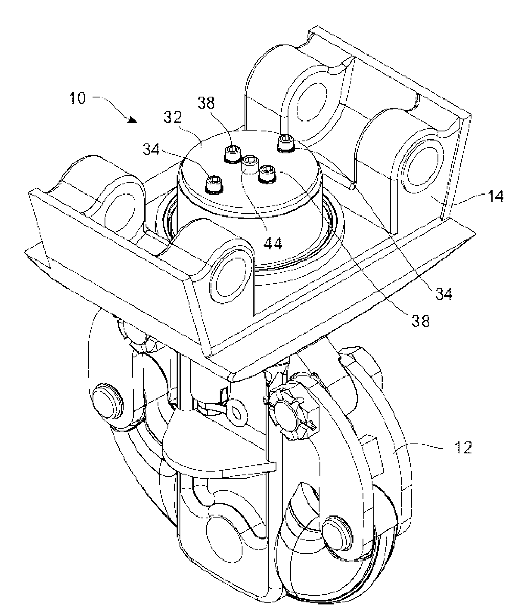
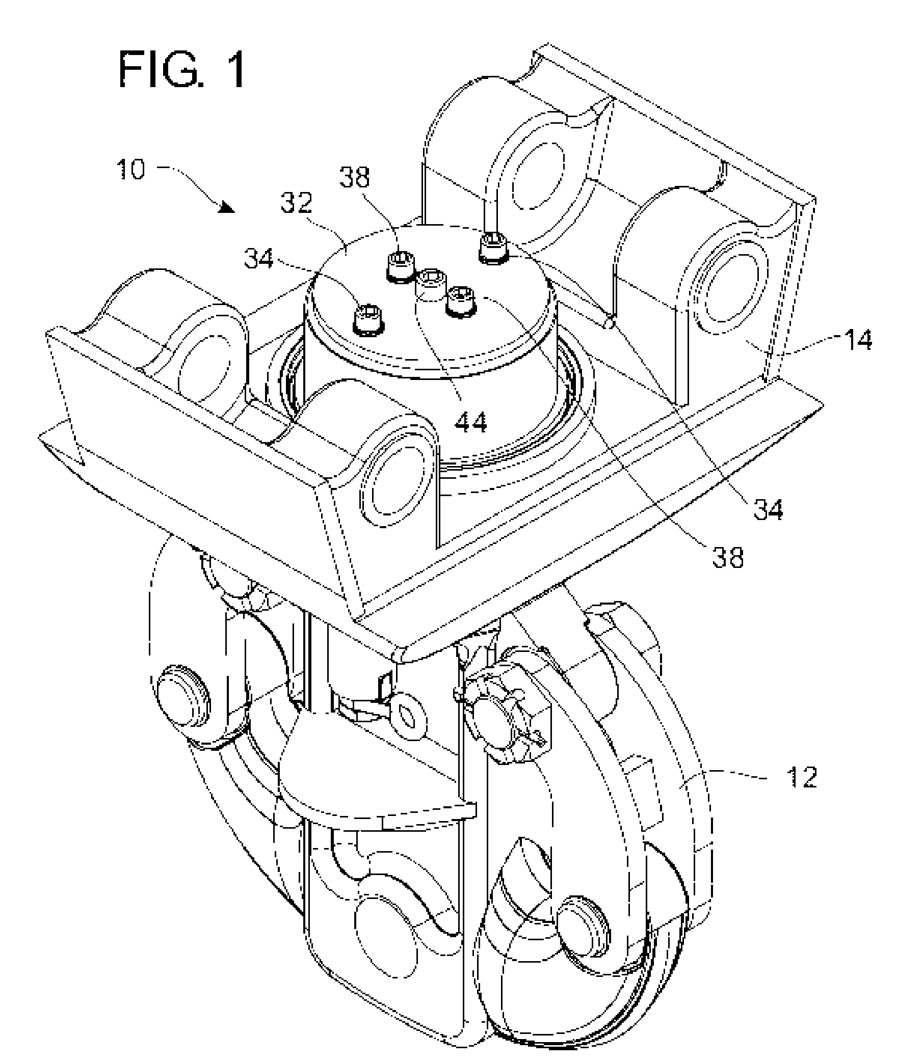
[0027]Referring to the drawings in detail, FIG. 1 is a perspective view of an initial preferred embodiment of a retaining keeper assembly 10 shown in use with a hoisting device. In a preferred embodiment of the present invention displayed, a tubing block with a hook 12 used for oilfield tubing applications is shown. It will be appreciated that other types of hooks, shackles or lifting dev...


PUM


Abstract

A retaining keeper assembly for a hoisting device. A shank has a plurality of circumferential grooves perpendicular to an axis of the shank. A thrust bearing surrounds the shank and is supported by the hoisting device. A split retaining collar having a plurality of interior circular protrusions mates with the circumferential grooves in the shank to prevent axial movement of the shank. A cylindrical retaining keeper ring having an open top and an open bottom encloses the assembled retaining collar, the keeper ring having an inner diameter slightly larger than an outer diameter of the retaining collar. A pair of retaining rings surround the split retaining collar above and below the keeper ring to trap the keeper ring in place.

Description

CROSS REFERENCE TO PENDING APPLICATIONS[0001]This is a continuation-in-part patent application of U.S. patent application Ser. No. 10 / 634,255 filed Aug. 5, 2003 now U.S. Pat. No. 7,000,905 entitled “Retaining Keeper Assembly for a Hoisting Device”.BACKGROUND OF THE INVENTION[0002]1. Field of the Invention[0003]The present invention relates to a retaining keeper assembly for a hoisting device. In particular, the present invention relates to a retaining keeper assembly for a pulley block that will accommodate rotating swivel action and be sealed from the elements while also permitting easy disassembly and reassembly.[0004]2. Prior Art[0005]In various types of industrial hoisting devices, it is necessary and desirable to swivel or rotate a load receiving member such as a hook, shackle or the like, with a hoisting portion, such as a pulley block. Examples of prior assemblies in hoisting devices are shown in Assignee's (The Crosby Group, Inc.) U.S. Pat. No. 4,669,907 entitled “Industrial...

Claims


Application Information

Patent Timeline
Patent Type & Authority Patents(United States)
IPC IPC(8): B66D3/04
CPCB66C1/34E21B19/02F16G15/08Y10T403/32598Y10T403/583Y10T403/32213Y10T403/69F16B2200/69
Inventor LUTTER, ERNEST E.DOUGHTY, ALAN C.BOECKMAN, PAUL A.
Owner CROSBY GROUP
Why Eureka
Try Eureka