Power generation assemblies, and apparatus for use therewith

a technology for power generation assemblies and apparatus, applied in the direction of wind energy generation, parallel air flow wind motors, wind energy generators, etc., can solve the problems of offensive presence of man-made objects in such areas, esthetic problems, and farm owners who are attracted to the same types of controversy

Active Publication Date: 2007-11-13
OCEAN WIND TECH
View PDF22 Cites 90 Cited by
  • Summary
  • Abstract
  • Description
  • Claims
  • Application Information

AI Technical Summary

Benefits of technology

[0016]Desirably, in such an anchored floating assembly, the center of gravity of the floating unit is at least about 30 meters below the water surface. and the floating unit desirably has a metacentric height (the distance between its centers of gravity and buoyancy) of at least about 10 meters. Also, the anchored floating assembly may further comprise at least two auxiliary cables extending from the buoyancy section to the cables connecting the base section to other components of the assembly, or to other components of the assembly. The base section of the mast may be provided with a peripheral hoop arranged to increase the hydrodynamic mass of the floating unit and to lengthen the natural heave period thereof. The mast may have a portion of reduced cross-section at the water surface, and the portion of the mast lying below the water surface may be provided with at least one ballast tank.
[0019]clamping the mast with the clamping members, thereby holding the mast in a substantially horizontal position above the deck;
[0023]In this “deployment process” of the present invention, the mast may comprise at least one ballast tank and the process may further comprise at least partially filling the ballast tank with water after pivoting the mast to a substantially vertical position but before releasing the mast from the clamping members. The deployment process may further comprise placing an external floatation device on the mast while the mast is in its substantially horizontal position above the deck, and releasing the external floatation device from the mast after the floating unit is floating. Also, at least one of the clamping members may be movable relative to the base member, thereby allowing the spacing between the clamping members to be varied. Finally, the vessel may be provided with means for varying the position of the axis of rotation of the pivotable unit relative to the deck.
[0024]Finally, this invention provides a wind turbine assembly comprising a plurality of cells, each cell having substantially the form of a hexagonal prism with a horizontal axis, each cell having a turbine mounted for rotation about an axis substantially coincident with the axis of the cell, the cells being disposed adjacent each other with their axes substantially parallel, each cell having a wall defining a passage through the cell, the turbine of the cell being located with this passage, the cross-section of the passage varying from a substantially hexagonal inlet to a substantially circular portion of minimum cross-sectional area adjacent the turbine, such that wind entering the inlet is accelerated before passing the turbine.

Problems solved by technology

Unfortunately, although wind farms are environmentally advantageous in the sense of not emitting pollutants, they do pose esthetic problems.
Furthermore, such mountain ridges or plains are often in areas celebrated for their natural beauty and many people find the presence of conspicuous man-made objects in such areas offensive.
However, such shallow water wind farms have attracted the same types of controversy as land-based wind farms.
For example, a recent proposal to place a large wind farm of more than 100 units in Nantucket Sound off the coast of Massachusetts has led to objections that the wind farm will be visible from popular beaches and from people engaged in recreational boating, and that the masts and rotors may cause vibrations which will affect commercial fishing and lobster trapping.
It has also been alleged that the rotors may kill or injure substantial numbers of birds.
Public controversy relating to wind farms would be reduced by moving off-shore wind farms a greater distance off-shore, although the maximum distance off-shore where wind farms can be located is limited by the expense of the undersea high voltage cables required to bring the electricity generated on-shore; such cables can incur very significant costs.
Moreover, the choice of suitable off-shore locations for wind farms, even relatively close to shore, is limited by water depth.
However, to justify the high costs of deeper water wind farms, such farms will typically be required to have high power outputs, and the conventional type of single mast / single rotor wind turbine with very large rotors may not be well adapted for mounting upon a floating or tension leg platform.

Method used


Image

  • Power generation assemblies, and apparatus for use therewith
  • Power generation assemblies, and apparatus for use therewith
  • Power generation assemblies, and apparatus for use therewith

Examples


Embodiment Construction

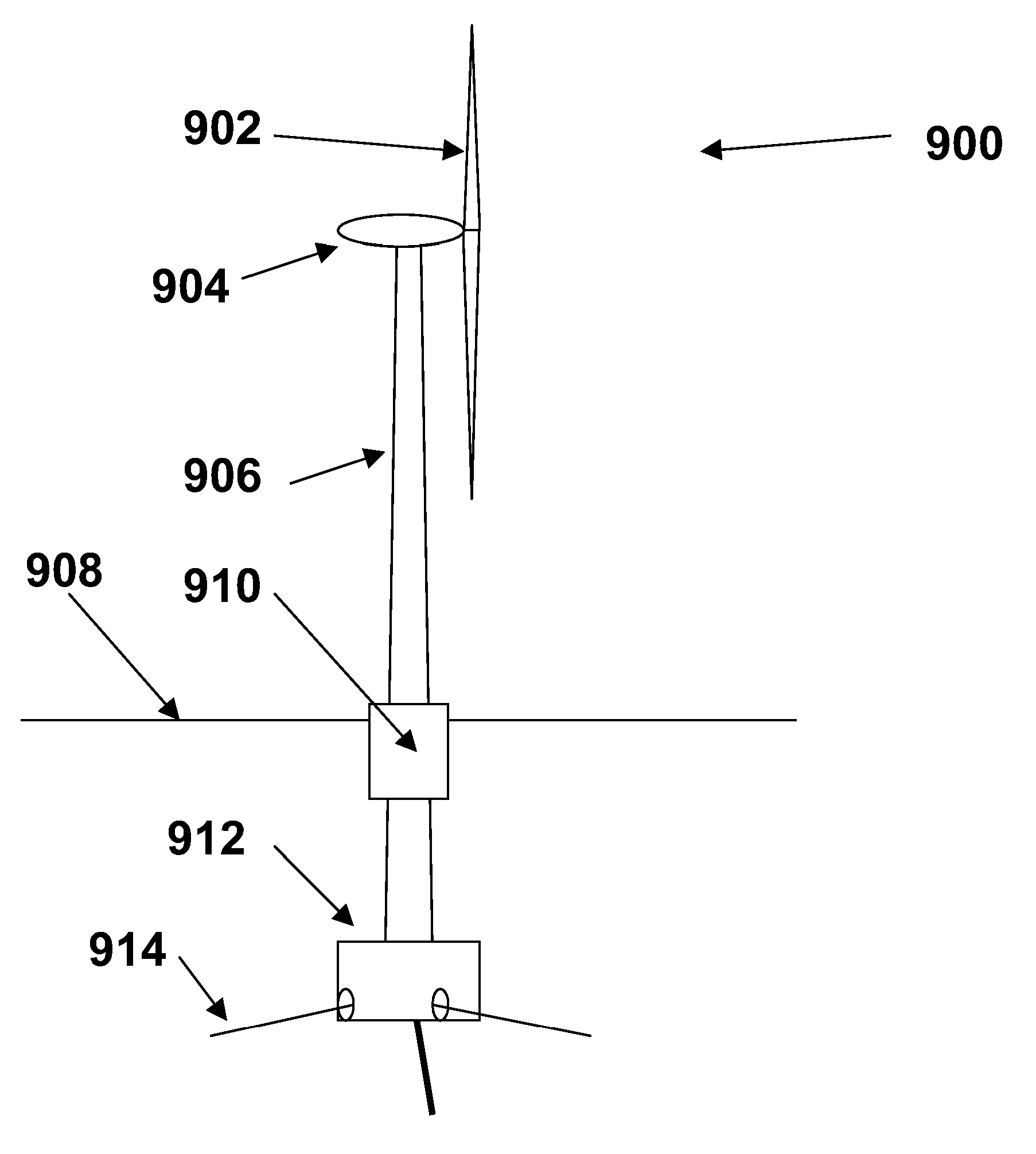
[0062]As already indicated, the present invention has three main aspects, namely a floating power generation assembly, a deployment process, and a cellular wind turbine assembly. These three aspects of the invention will mainly be described separately below, but it will be appreciated that a single assembly or process may make use of multiple aspects of the invention. For example, a floating power generation assembly may include cellular wind turbine assemblies of the invention, and the floating units of the floating power generation assembly may, and indeed are primarily intended to be, placed on site by the deployment process of the invention.

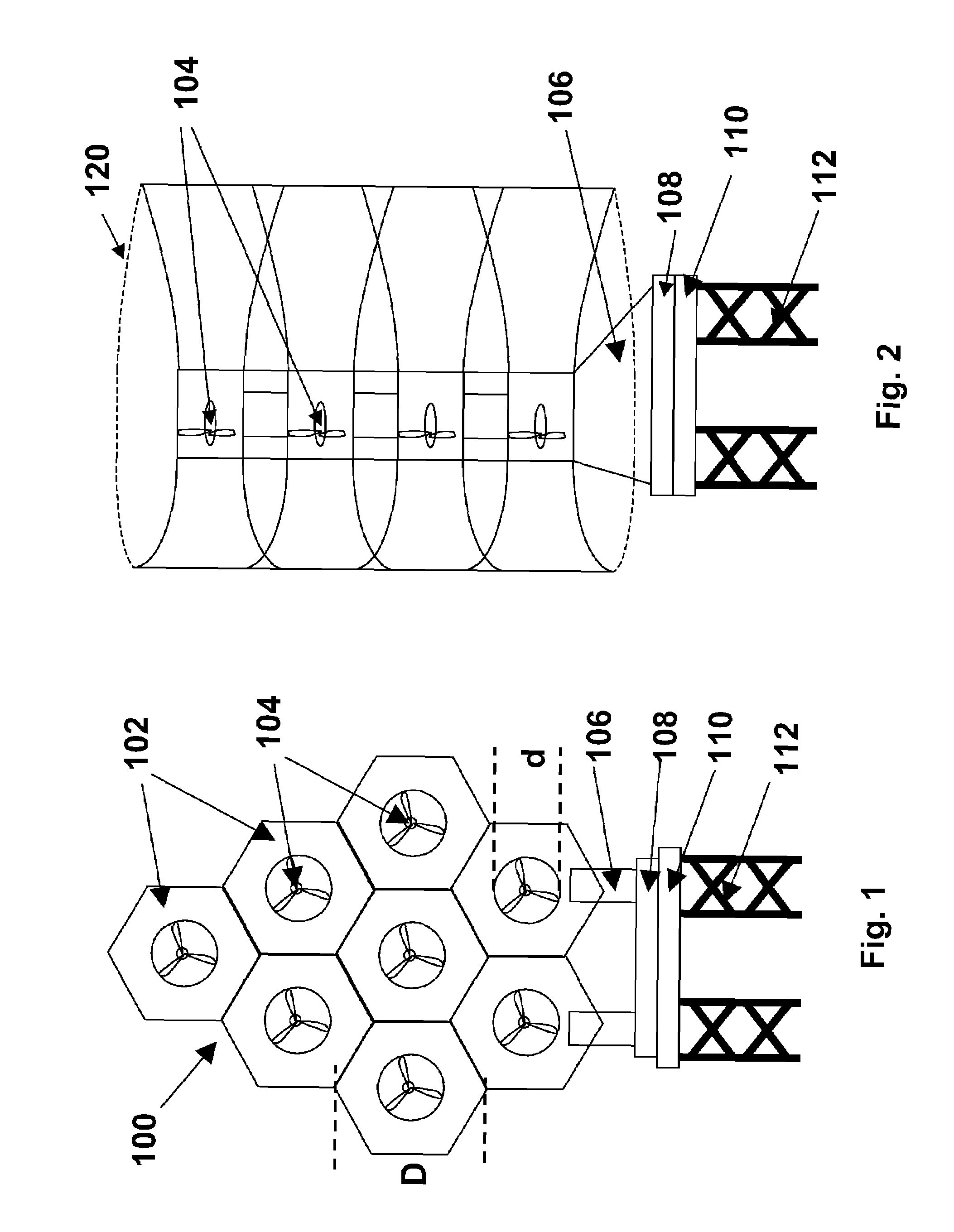
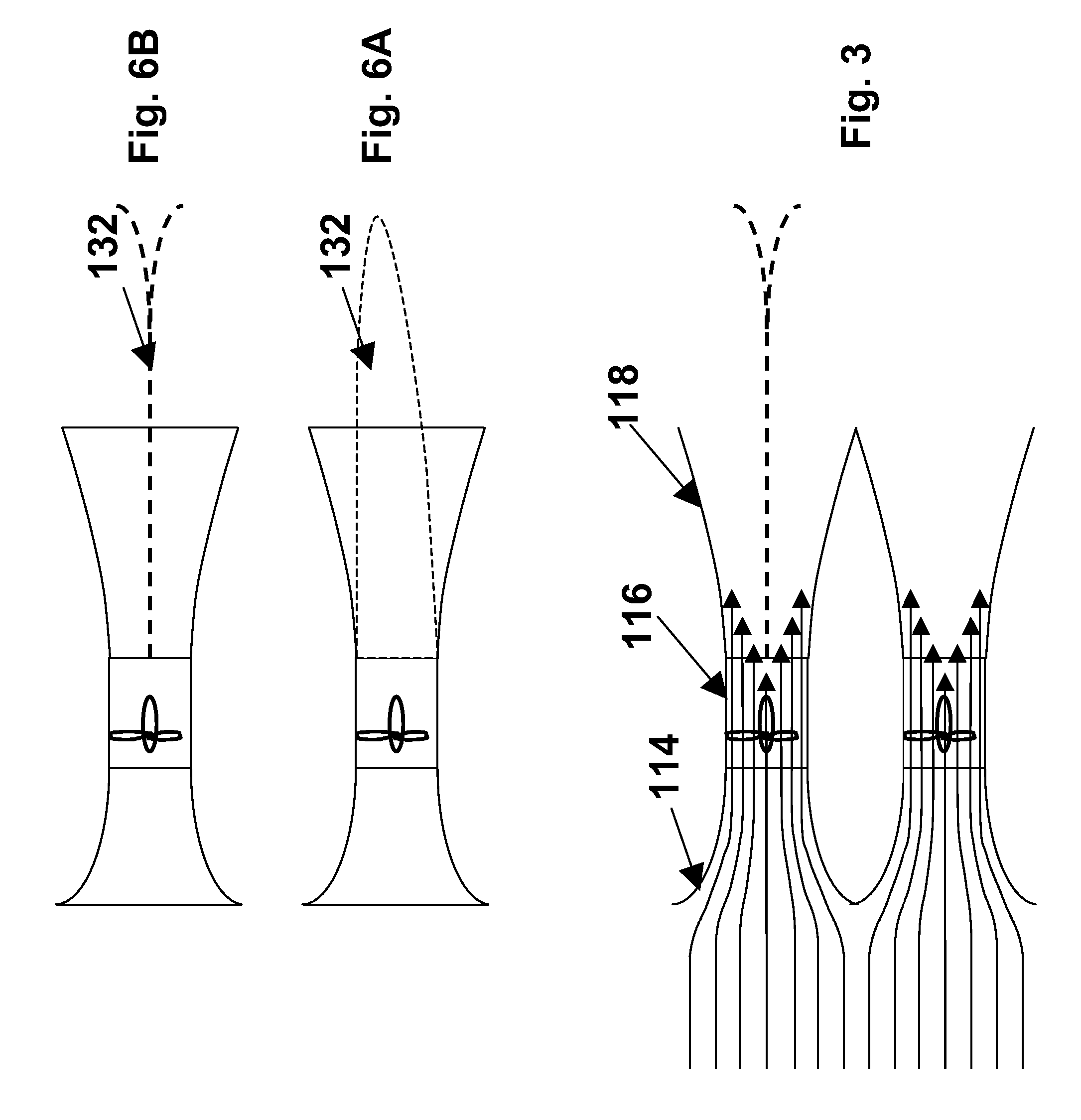
[0063]One form of the wind turbine assembly of the present invention, which might be used in a land-based wind farm, will now be described in detail with reference to FIGS. 1 to 3 of the accompanying drawings, in which FIG. 1 is a schematic front elevation of the preferred wind turbine assembly (generally designated 100), FIG. 2 is a schemati...


PUM


Abstract

A floating power generation assembly comprises at least three floating units (900) floating on a body of water, and at least three anchors (916) secured to a solid surface beneath the body of water, each of the floating units (900) being provided with a power generator, the floating units (900) being arranged substantially at the vertices of at least one equilateral triangle. Ship borne apparatus for deploying the floating units of such a power generation assembly and a novel multiple wind turbine assembly are also described.

Description

REFERENCE TO RELATED APPLICATION[0001]This application claims priority from Provisional Application Ser. No. 60 / 481,547, filed Oct. 23, 2003, the entire disclosure of which is herein incorporated by reference.BACKGROUND OF THE INVENTION[0002]This invention relates to power generation assemblies, and apparatus for use therewith. More specifically, this invention relates to (a) a floating power generation assembly; (b) a process for placing a floating unit on water, this process being especially, although not exclusively, intended for use in deploying certain components of the floating power generation assembly of the invention; and (c) a multiple wind turbine assembly.[0003]As concern over the environmental consequences of conventional power plants, including their carbon dioxide emissions, has increased in recent years, greater attention has been focused upon so-called “green” or environmentally advantageous power plants which use renewable sources of energy and do not cause substan...

Claims


Application Information

Patent Timeline
Patent Type & Authority Patents(United States)
IPC IPC(8): F03D1/00F03D11/04F03DF03D9/00
CPCF03D1/02F03D11/04F03D1/001F03D1/04F03D9/008B63B2039/067F05B2210/18F05B2240/13F05B2240/40F05B2240/93F05B2240/95F05B2240/96F05B2250/132Y02E10/38Y02E10/721Y02E10/725Y02E10/727Y10S416/04Y10S416/06B63B2035/446B63B21/50F03D13/10F03D13/25F03D13/40Y02E10/30Y02E10/72
Inventor YAMAMOTO, SHIGEYUKICOLBURN, JR., WARREN E.
Owner OCEAN WIND TECH
Why Eureka
Try Eureka