Discharge tube lighting apparatus, light source apparatus, and display apparatus

a technology of discharge tube and light source, which is applied in the direction of instruments, basic electric elements, light sources, etc., can solve the problems of excessive high voltage generation across the windings of the balance coil, ineffective drive of a plurality of discharge tubes individually, and excessive current flowing through the discharge tubes. to prevent otherwise possible damage to the circuit board and the balance coil

Inactive Publication Date: 2007-11-13
SONY CORP
View PDF11 Cites 28 Cited by
  • Summary
  • Abstract
  • Description
  • Claims
  • Application Information

AI Technical Summary

Benefits of technology

[0012]The discharge tube lighting apparatus further includes a control section for detecting a peak value of detection voltages corresponding to voltages at the winding output ends of the balance coil and for stopping the supply of the ac current from the power section when the peak value of the detection voltages is higher than a predetermined value, and prevents otherwise possible damage to a circuit board and to the balance coil.
[0016]The light source apparatus further includes a control section for detecting a peak value of detection voltages corresponding to voltages at the winding output ends of the balance coil and for stopping the supply of the ac current from the power section when the peak value of the detection voltages is higher than a predetermined value, and prevents otherwise possible damage to a circuit board and to the balance coil.
[0018]The display apparatus includes a liquid crystal display panel having an image display face for displaying image information; a discharge tube section disposed on a rear face of the liquid crystal display panel opposite the image display face; and a discharge tube lighting apparatus for driving the discharge tube section. The discharge tube lighting apparatus includes a balance coil having a winding input end and a plurality of winding output ends; and a power section for supplying ac current to the winding input end of the balance coil, and causes uniform current to flow through the discharge tubes by an action of the balance coil. The display apparatus further includes a control section for detecting a peak value of detection voltages corresponding to voltages at the winding output ends of the balance coil and for stopping the supply of the ac current from the power section when the peak value of the detection voltages is higher than a predetermined value, and prevents otherwise possible damage to a circuit board and to the balance coil.
[0019]With the discharge tube lighting apparatus, light source apparatus, and display apparatus, the problems which may possibly be estimated to occur where a balance coil is used can be prevented. For example, the problems may be burning of the balance coil or carbonization of a circuit board by heat generation from the circuit board.

Problems solved by technology

However, it is not efficient to drive a plurality of discharge tubes individually by means of driving circuits provided individually for the discharge tubes.
Where a plurality of discharge lamps are driven to emit light by a single inverter circuit in this manner, there is a problem that electric current of different magnitudes flows through the discharge tubes.
Where a balance coil is used, if one of discharge tubes does not discharge, then an excessively high voltage is generated across windings of the balance coil and damages the windings of the balance coil.
However, if a line connecting from the balance coil to one of the discharge tubes is not connected by breaking of a wiring line pattern, failure in connection of a connector, or the like, then it is supposed that a high voltage is generated in the wiring line of the balance coil which corresponds to the disconnected line.
In such an instance, there is the possibility that a discharge phenomenon may occur between wiring patterns, between the windings of the balance coil, or between the wiring and the core which form a magnetic circuit, whereupon a stench is given off, the balance coil may burn out, or a printed circuit board may be carbonized.
However, application of a voltage to the diac continues for a long period of time, there is the possibility that the diac may be damaged, resulting in loss of the protection of the same.
Further, a detection circuit which uses a photo-coupler can merely detect an abnormal voltage across a winding of a balance coil, but no measures after detection of an abnormal voltage is taken.

Method used


Image

  • Discharge tube lighting apparatus, light source apparatus, and display apparatus
  • Discharge tube lighting apparatus, light source apparatus, and display apparatus
  • Discharge tube lighting apparatus, light source apparatus, and display apparatus

Examples


Embodiment Construction

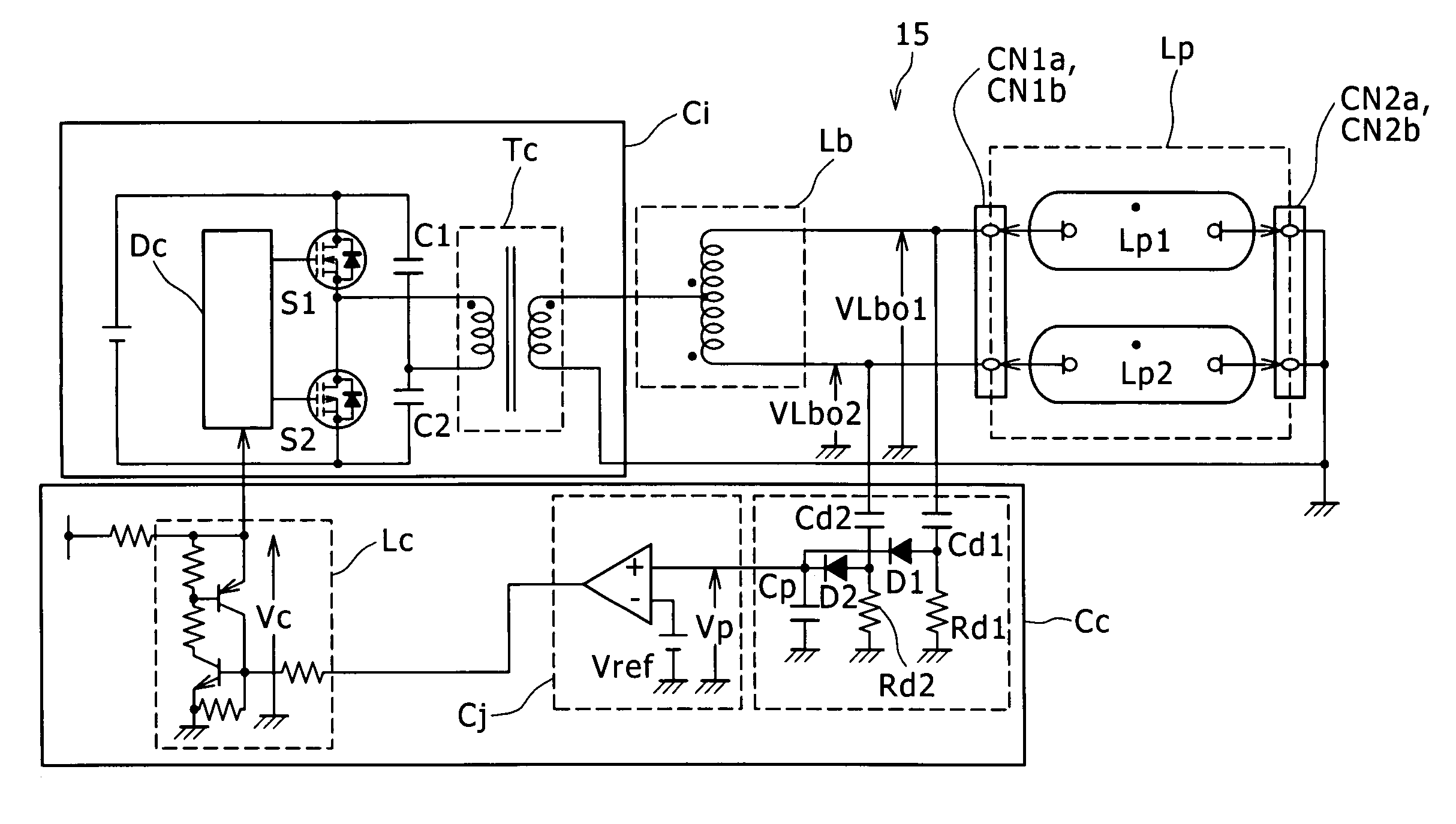
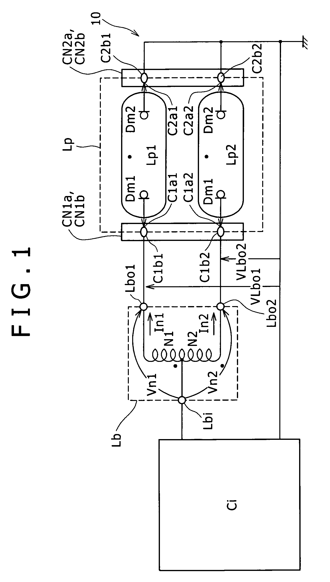
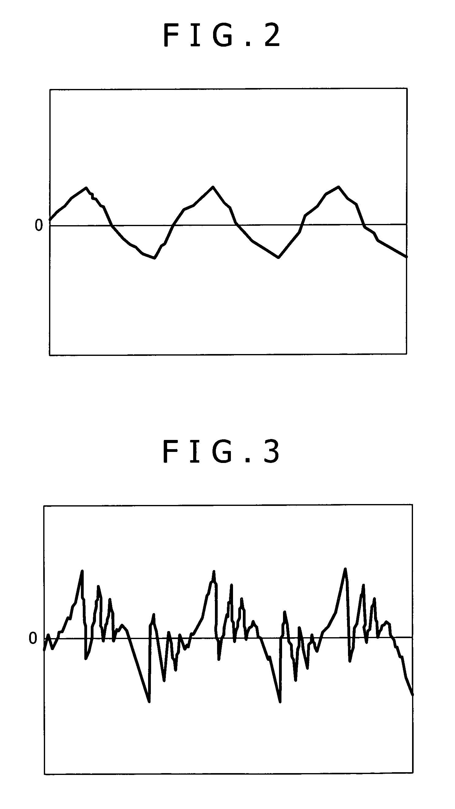
[0030]FIGS. 1 to 3 illustrate an example of operation of a balance coil Lb of a light source apparatus 10 to which an embodiment of the present invention is applied. Referring first to FIG. 1, the light source apparatus 10 shown includes a discharge tube lighting apparatus which includes an inverter circuit Ci, which is a form of a power section, and a balance coil Lb. A discharge tube section Lp is formed from a discharge tube Lp1 and another discharge tube Lp2. Each of the discharge tubes Lp1 and Lp2 has a conductive electrode Dm1 and another conductive electrode Dm2. Each of the conductive electrodes Dm1 is connected to a connector CN1a through a wiring line, and each of the conductive electrodes Dm2 is connected to another connector CN2a through a wiring line. Meanwhile, a connector CN1b which is used in combination with the connector CN1a is connected to winding output ends Lbo1 and Lbo2 of the balance coil Lb, and another connector CN2b which is used in combination with the co...


PUM


Abstract

A discharge tube lighting apparatus is used to drive a plurality of discharge tubes. The apparatus includes a balance coil having a winding input end and a plurality of winding output ends to which the discharge tubes are connected individually; a power section for supplying ac current to the winding input end of the balance coil; and a control section for detecting a peak value of detection voltages corresponding to voltages at the winding output ends of the balance coil and for stopping the supply of the ac current from the power section when the peak value of the detection voltages is higher than a predetermined value.

Description

CROSS-REFERENCE TO RELATED APPLICATIONS[0001]The present application claims priority from Japanese Patent Application Nos. JP 2005-137055 filed May 10, 2005 and JP 2006-081287 filed on Mar. 23, 2006, the disclosures of which are hereby incorporated by reference herein.BACKGROUND OF THE INVENTION[0002]This invention relates to a discharge tube lighting apparatus, a light source apparatus, and a display apparatus, and more particularly to a discharge tube lighting apparatus which includes a balance coil for driving a large number of discharge tubes to emit light using a smaller number of inverter circuits and a light source apparatus and a display apparatus which use a discharge tube lighting apparatus.[0003]In recent years, image display apparatus which make use of liquid crystal are used popularly. A display apparatus of the type described requires a light source apparatus for irradiating light from the rear side of a liquid crystal panel, and such a light source apparatus as just m...

Claims


Application Information

Patent Timeline
Patent Type & Authority Patents(United States)
IPC IPC(8): H05B37/02
CPCH05B41/282H05B41/2822Y10S315/07H05B41/26H05B41/36
Inventor TAKAHAMA, MASANOBUOYAMA, YOSHIKI
Owner SONY CORP
Why Eureka
Try Eureka