Eureka AIR delivers breakthrough ideas for toughest innovation challenges, trusted by R&D personnel around the world.

Method for calculating colorant error from reflectance measurement

a reflectance measurement and colorant error technology, applied in the field of color measurement, can solve the problems of difficult conversion of three-dimensional color space color measurements to four-dimensional dimensions, inconvenient use, and inability to readily be found

Inactive Publication Date: 2007-11-13
XEROX CORP
View PDF31 Cites 10 Cited by
  • Summary
  • Abstract
  • Description
  • Claims
  • Application Information

AI Technical Summary

Problems solved by technology

However, color sensors that report color in four color space dimensions (e.g., CMYK) are not readily available and converting three dimensional color space color measurements to four dimensions is problematic.
Due to this uncertainty, there has been no known (general) method to convert from a difference between the measured (scanned) trichromatic values and desired trichromatic values to a difference between the specified or input colorant values (typically CMYK) and the amount of CMYK that actually or apparently adhered to a target sheet or page.
However, this adds to system design, manufacturing and servicing costs.

Method used


Image

  • Method for calculating colorant error from reflectance measurement
  • Method for calculating colorant error from reflectance measurement
  • Method for calculating colorant error from reflectance measurement

Examples


second embodiment

[0062]In a second embodiment, the predetermined 108 mapping takes the form of a color printer characterization encoded as a table mapping from CMYK to RGB. Processing proceeds in a similar manner. However, certain of the equations and structures are adjusted accordingly.

[0063]For example, in these embodiments, calculating 146 the rendering error can include differentiating the mapping from CMYK to RGB in all dimensions, yielding a matrix (Jacobian) of the form

[0064]M=[∂R∂c∂R∂m∂R∂y∂R∂k∂G∂c∂G∂m∂G∂y∂G∂k∂B∂c∂B∂m∂B∂y∂B∂k]=[MRcMRmMRyMRkMGcMGmMGyMGkMBcMBmMByMBk](12)

[0065]Given the matrix M derived from the derivative table and the predetermined 108 mapping, we can determine for any given received 112 input CMYK the expected RGB (C1) and the measured RGB (C2). The difference, then, is given by ΔC=C2−C1=(ΔR, ΔG, ΔB)T.

[0066]Now define x as the vector (Δc, Δm, Δy, Δk)T, which is the difference between the intended and actual CMYK. Given a smooth, continuous characterization function, perfectly...

third embodiment

[0085]In a third embodiment, in addition to a predetermined 108 mapping from CMYK to RGB there is an additional mapping from RGB to L*a*b*. Information from these two mappings can be used to predetermine 108 a mapping from CMYK to L*a*b*. This gives us two ways of obtaining L*a*b*: first, we can convert the input (i.e., received 112) CMYK values, and second, we can convert measured RGB values. By converting received 112 and measured 126 color descriptions to L*a*b* we can obtain a color difference vector ΔC as before, only this time it is computed as (L*2−L*1, a*2−a*1, b*2−b*1). Applying all of the same mathematics as described above, with this version of color difference vector, may produce an improved effect, as the difference is calculated in a visually meaningful space.

[0086]It should be noted that, while the above description assumes one must compute the Jacobian matrix M from information in an original mapping (e.g. from CMYK to L* a* b* or RGB), having the original mapping is...


PUM


Abstract

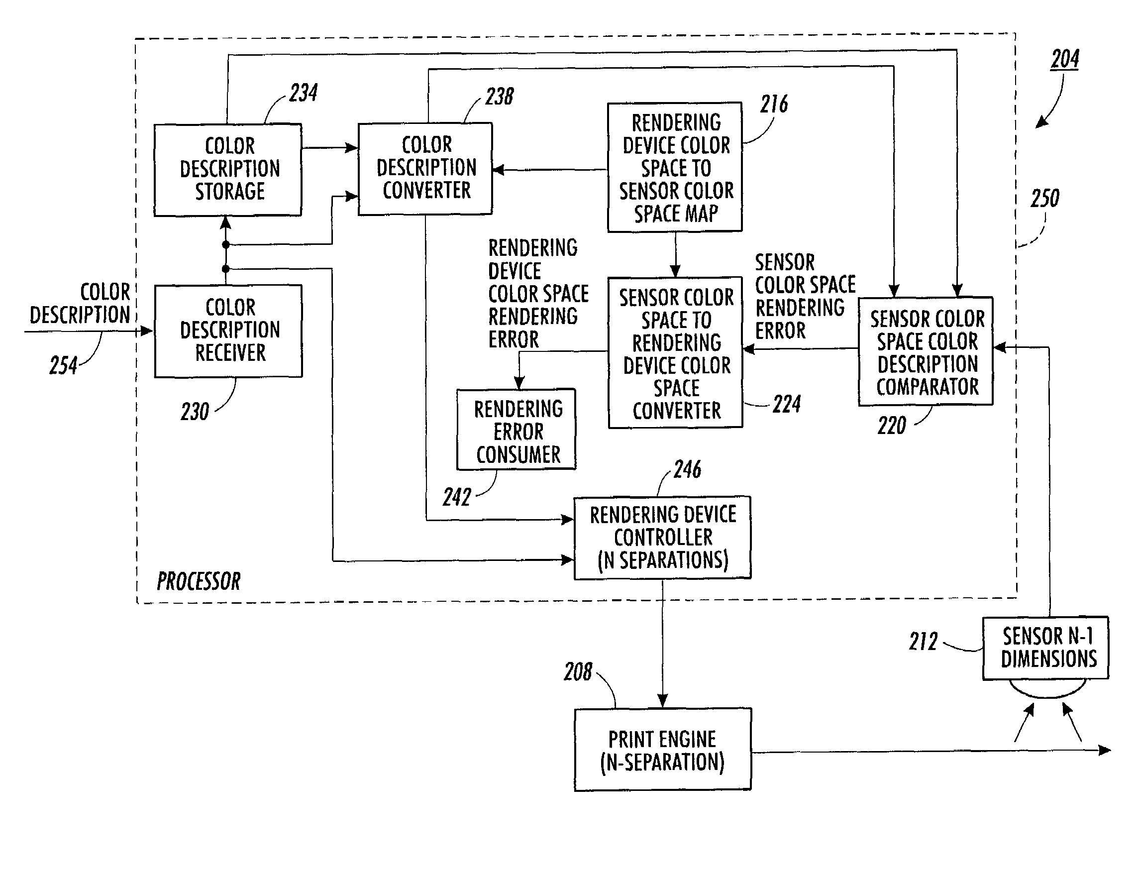
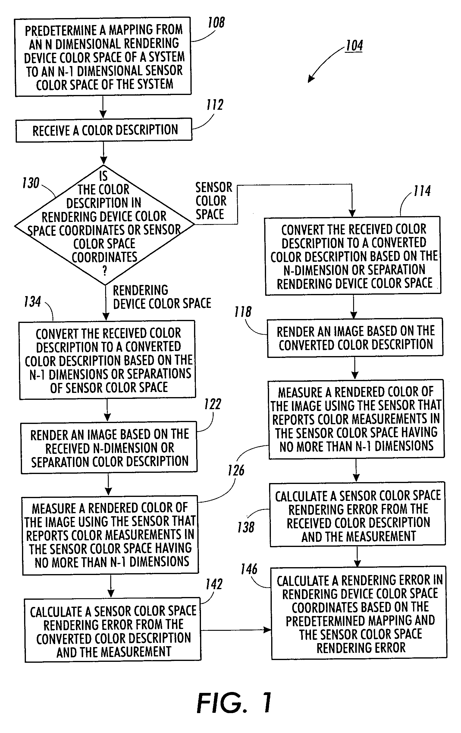
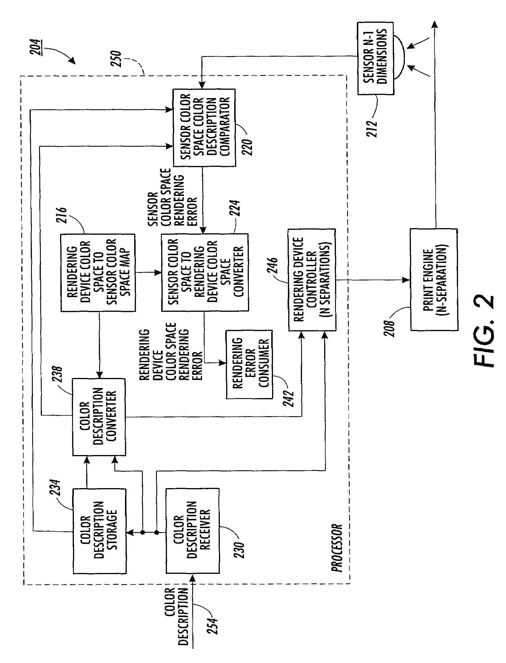
Color error associated with an image rendered by a rendering device is calculated in the no more than N−1 dimensions of an associated color sensor color space. The color error is assumed to be small. A differential of a mapping from an N dimensional rendering device color space to the associated color sensor color space is used to calculate a colorant error in the N dimensions of the rendering device color space. Where necessary, appropriate assumptions are used to constrain an underdetermined system of equations. Where calculated colorant error is unreasonable, the calculated colorant error is clipped and colorant error is recalculated based on the clipped value.

Description

BACKGROUND[0001]The present exemplary embodiment relates to color measurement. It finds particular application in conjunction with image rendering devices wherein colors are rendered with a higher number of colorants or color dimensions than are included in an available color measurement signal, and will be described with particular reference thereto. However, it is to be appreciated that the present exemplary embodiment is also amenable to other like applications.[0002]Most readily available color sensors are based on the three primary colors (i.e.; red, green and blue). Light reflected from an image or object is filtered or refracted according to its wavelength. Light sensors such as photo diodes and photo transistors or charge coupled devices are positioned to receive the filtered or refracted light. The sensors generate signals according to the intensity of the light that reaches them. Some sensors report these color signals in terms of red, green and blue intensities. Other sen...

Claims


Application Information

Patent Timeline
Patent Type & Authority Patents(United States)
IPC IPC(8): G09G5/02G06K9/00
CPCH04N1/6033
Inventor KLASSEN, R. VICTOR
Owner XEROX CORP
Why Eureka
Eureka Blog
Learn More