System and method for scheduling message transmission and processing in a digital data network

a digital data network and message transmission technology, applied in the field of digital communication systems, can solve the problems of slow information transfer, inability to use other devices connected thereto, complex network, etc., and achieve the effect of fair message transmission, fair message processing, and fair message transmission

Inactive Publication Date: 2007-11-13
GIGANET
View PDF20 Cites 5 Cited by
  • Summary
  • Abstract
  • Description
  • Claims
  • Application Information

AI Technical Summary

Benefits of technology

[0006]In brief summary, the invention in one embodiment provides a system comprising at least two devices interconnected by a network including at least one communication link. Each device includes a network interface for transferring messages over the network. At least one of the devices as a source device, transmits messages over one or more virtual circuits established over the network, and at least one other of said devices, as a destination device for the respective virtual circuits, receives the messages thereover. The network interface of the source device includes a transmit section that includes a transmitter and a transmit scheduler. The transmitter generally transmits messages for the respective virtual circuits for which the device is the source device. The transmit scheduler schedules transmission of messages by the transmitter so that messages are transmitted in a round-robin manner as among the virtual circuits for which the device is the source device, thereby providing fairness in message transmission as among the virtual circuits. In one embodiment, the transmitter transmits messages in a series of fixed-length cells, each of which can contain a portion of a message, and the transmit scheduler schedules transmission of messages by the transmitter so that messages are transmitted in a round-robin manner as among the virtual circuits for which the device is the source device, so that short messages for ones of the virtual circuits are not unduly delayed by relatively long messages for others of the virtual circuits. The network interface of the destination device includes a receive host for performing predetermined operations in connection with receive messages, and a receive scheduler. The receive scheduler schedules the virtual circuits for which the device is the destination device and enables the receive host to perform the predetermined operations in connection with the virtual circuits for which the device is the destination device in a round-robin manner, thereby providing fairness in message processing as among the virtual circuits.
[0007]In another embodiment, the network includes a switching node which forms part of the path for one or more virtual circuits between the source device and the destination device. The switching node is connected to receive messages transmitted by the source device over the virtual circuit(s) for which it forms part of the path over one communication link connected thereto, buffer the received messages in an internal buffer, and transmit the buffered messages over the virtual circuit(s) over another communication link connected thereto, thereby to forward messages for the virtual circuit(s) downstream over the respective virtual circuit(s). The switching node transmits the buffered messages over the virtual circuits generally in a round-robin manner for virtual circuits for which the respective communication link forms part of the path, thereby providing fairness in message transmission as among the virtual circuits.

Problems solved by technology

While this simplifies wiring of the network in a facility and connection of the devices to the network, it results in generally slow information transfer, since the wire can only carry information, in the form of messages, from a single device at a time.
It is only when a device connected to one wire needs to send a message to a device connected to another wire that wires in two or more sub-networks will be used, making them unavailable for use by other devices connected thereto.
Such an arrangement may result in a network which is more complicated than an Ethernet network, but it can provide substantially higher information transfer rates, particularly if optical fiber is used as the media interconnecting the switching nodes and devices.
A problem which may arise with such networks is that, in such networks, a switching node or a device, when it is receiving information from another switching node or device in the network, does not have a mechanism to provide “flow-control” information to the transmitting switching node or device.
While this does reduce the cost of a network, it may result in congestion, in which either a switching node may receive information at a rate faster than it can transmit it, or a destination device may receive information at a rate faster than it can buffer and process it.

Method used


Image

  • System and method for scheduling message transmission and processing in a digital data network
  • System and method for scheduling message transmission and processing in a digital data network
  • System and method for scheduling message transmission and processing in a digital data network

Examples


Embodiment Construction

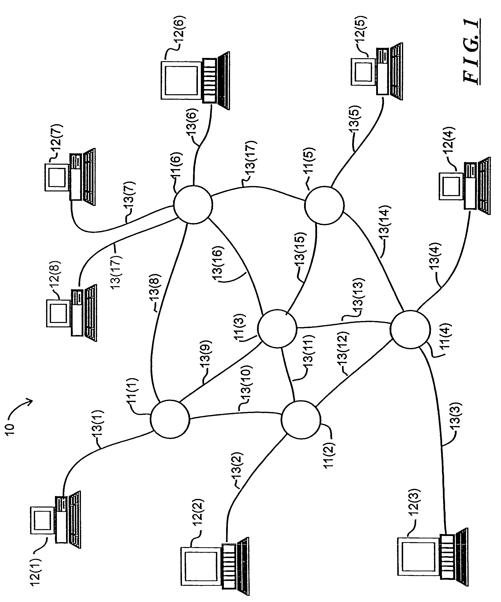
[0014]FIG. 1 schematically depicts a computer network 10 including a plurality of switching nodes 11(l) through 11(N) (generally identified by reference numeral 11(n)) for transferring signals representing data among a number of devices, which in FIG. 1 are represented by computers 12(1) through 12(M) (generally identified by reference numeral 12(m)). The computers 12(m), as is conventional, process data, in accordance with their program instructions to generate processed data. In their processing, a computer 12(mS) (subscript “S” referencing “source”) may, as a source computer, need to transfer data, processed data and / or program instructions (all of which will be referred to herein generally as “information”) to another, destination, computer 12(mD) (subscript “D” referencing “destination”), which may need to use the transferred information in its operations. Each computer 12(m) is connected over a communication link, generally identified by reference numeral 13(p), to a switching...


PUM


Abstract

A system includes a plurality of computers interconnected by a network including one or more switching nodes. The computers transfer messages over virtual circuits established thereamong. A computer, as a source computer for one or more virtual circuit(s), schedules transmission of messages on a round-robin basis as among the virtual circuits for which it is source computer. Each switching node which forms part of a path for respective virtual circuits also forwards messages for virtual circuits in a round-robin manner, and, a computer, as a destination computer for one or more virtual circuit(s), schedules processing of received messages in a round-robin manner. Round-robin transmission, forwarding and processing at the destination provides a degree of fairness in message transmission as among the virtual circuits established over the network. In addition, messages are transmitted in one or more cells, with the round-robin transmission being on a cell basis, so as to reduce delays which may occur for short messages if a long messages were transmitted in full for one virtual circuit before beginning transmission of a short message for another virtual circuit. For each virtual circuit, the destination computer and each switching node along the path for the virtual circuit can generate a virtual circuit flow control message for transmission to the source computer to temporarily limit transmission over the virtual circuit if the amount of resources being taken up by messages for the virtual circuit exceeds predetermined thresholds, further providing fairness as among the virtual circuits. In addition, each switching node or computer can generate link flow control messages for transmission to neighboring devices in the network to temporarily limit transmission thereto if the amount of resources taken up by all virtual circuits exceeds predetermined thresholds, so as to reduce the likelihood of message loss.

Description

CROSS-REFERENCE TO RELATED APPLICATION[0001]This application is a division of application Ser. No. 09 / 065,115 filed on Apr. 23, 1998 now U.S. Pat. No. 6,795,442, which application is specifically incorporated herein by reference, and which is related to previously filed U.S. patent application Ser. No. 09 / 065,118 (now U.S. Pat. No. 6,570,851) entitled “System and Method for Regulating Message Flow In A Digital Data Network”, both assigned to the same assignee as the present application.FIELD OF THE INVENTION[0002]The invention relates generally to the field of the digital communications systems and more particularly to digital networks for facilitating communication of digital data in, for example, digital image, audio and video distribution systems and among digital computer systems. The invention is more particularly directed to flow control and scheduling arrangements for regulating the flow of information through the network to avoid congestion, prevent loss of data and preserve...

Claims


Application Information

Patent Timeline
Patent Type & Authority Patents(United States)
IPC IPC(8): H04L12/56
CPCH04L12/5693H04L47/6215H04L49/9078H04L49/901H04L47/6225H04L47/50
Inventor CLAYTON, SHAWN A.FOLLETT, DAVID R.GODIWALA, NITIN D.GUTIERREZ, MARIA C.WELLS, DAVID S.WILLIAMS, JAMES B.
Owner GIGANET
Why Eureka
Try Eureka