Digital vertical level indicator for improving the aim of projectile launching devices

a projectile and vertical level technology, applied in the field of electronic vertical angle sensing and indicating devices, can solve the problems of projectile falling short, angle to be reduced slightly, and some limitations, so as to improve range accuracy and minimize the left-right drift of a projectile. , the effect of improving the vertical level measuremen

Active Publication Date: 2007-11-20
MURPHY PATRICK J +2
View PDF11 Cites 68 Cited by
  • Summary
  • Abstract
  • Description
  • Claims
  • Application Information

AI Technical Summary

Benefits of technology

[0010]In accordance with one aspect of the present invention, an electronic vertical angle sensing and indicating device for use on aiming systems is provided for bow sights and for other aiming sights for projectile launchers such as firearms and grenade launchers, etc. Improved vertical level measurement and display minimizes the left-right drift of a projectile by sensing and indicating to the user when the projectile launcher is tilted slightly prior to release of the projectile. Additionally, improved vertical level indications provided by the present invention will improve the range accuracy by ensuring that the vertical launch angle of the projectile is maintained at the vertical level to which the sights were initially set.

Problems solved by technology

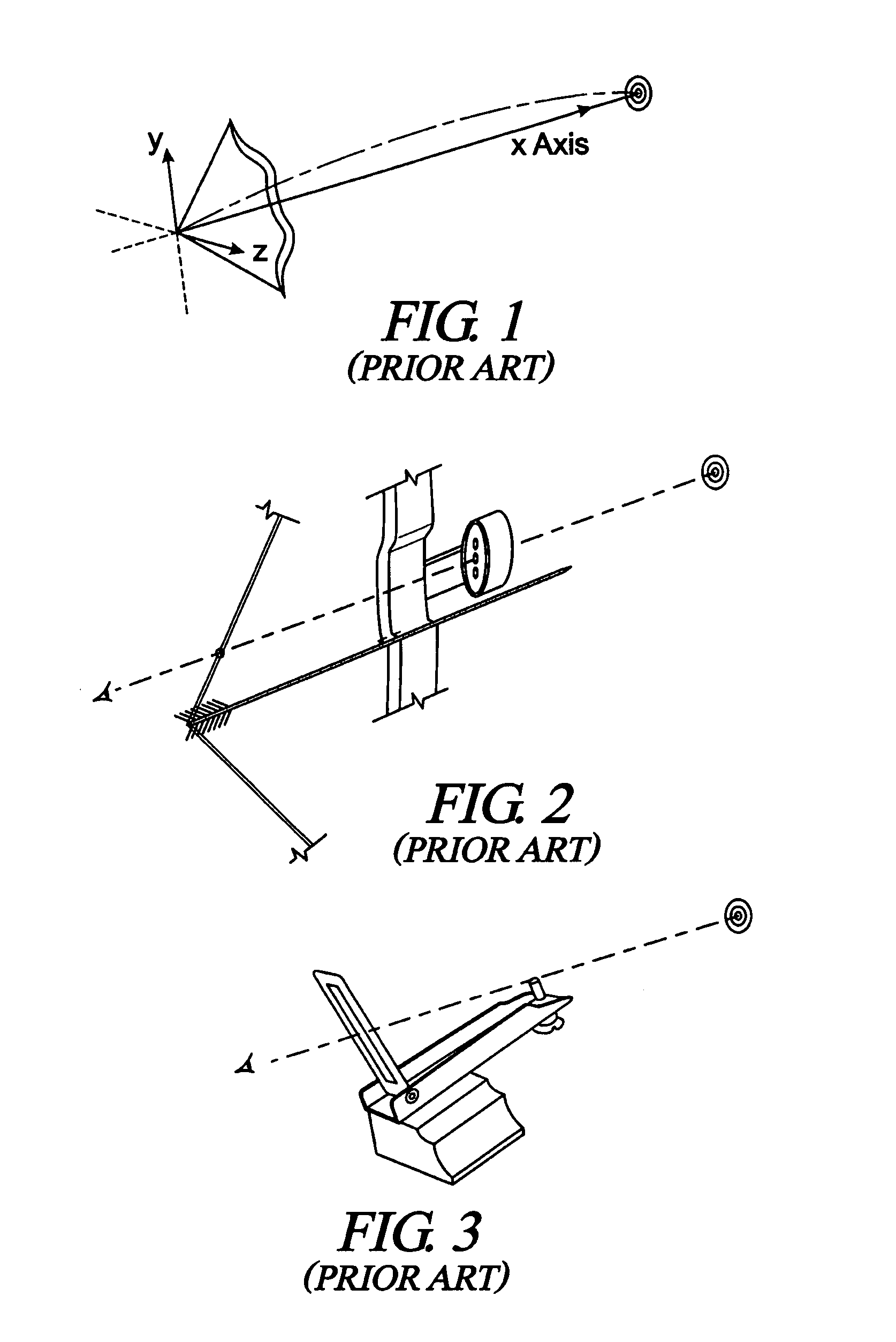
While bubble-type levels perform reasonably well for short trajectory shooting situations, they are somewhat limited when the arrow trajectory is long.
Simultaneously, the cant angle causes the launch angle to be reduced slightly, causing the projectile the fall short.
Aiming systems using either bubble-type levels or mechanical pendulum devices are bulky and cumbersome when used with portable projectile launchers such as bows and firearms.
This is especially true when an angle sensing device is attached to bowsights, because of the high amount of shock and vibration generated during the process of shooting of an arrow.
Excessive mass attached to such a bowsight can cause extreme stresses on the sight frame, eventually causing the bowsight attachment point to fatigue and fracture.
While providing a binary indication of vertical level, these devices do not provide for analog or digital output signals that are proportional to the cant angle.

Method used


Image

  • Digital vertical level indicator for improving the aim of projectile launching devices
  • Digital vertical level indicator for improving the aim of projectile launching devices
  • Digital vertical level indicator for improving the aim of projectile launching devices

Examples


Embodiment Construction

I. Accelerometer Operation

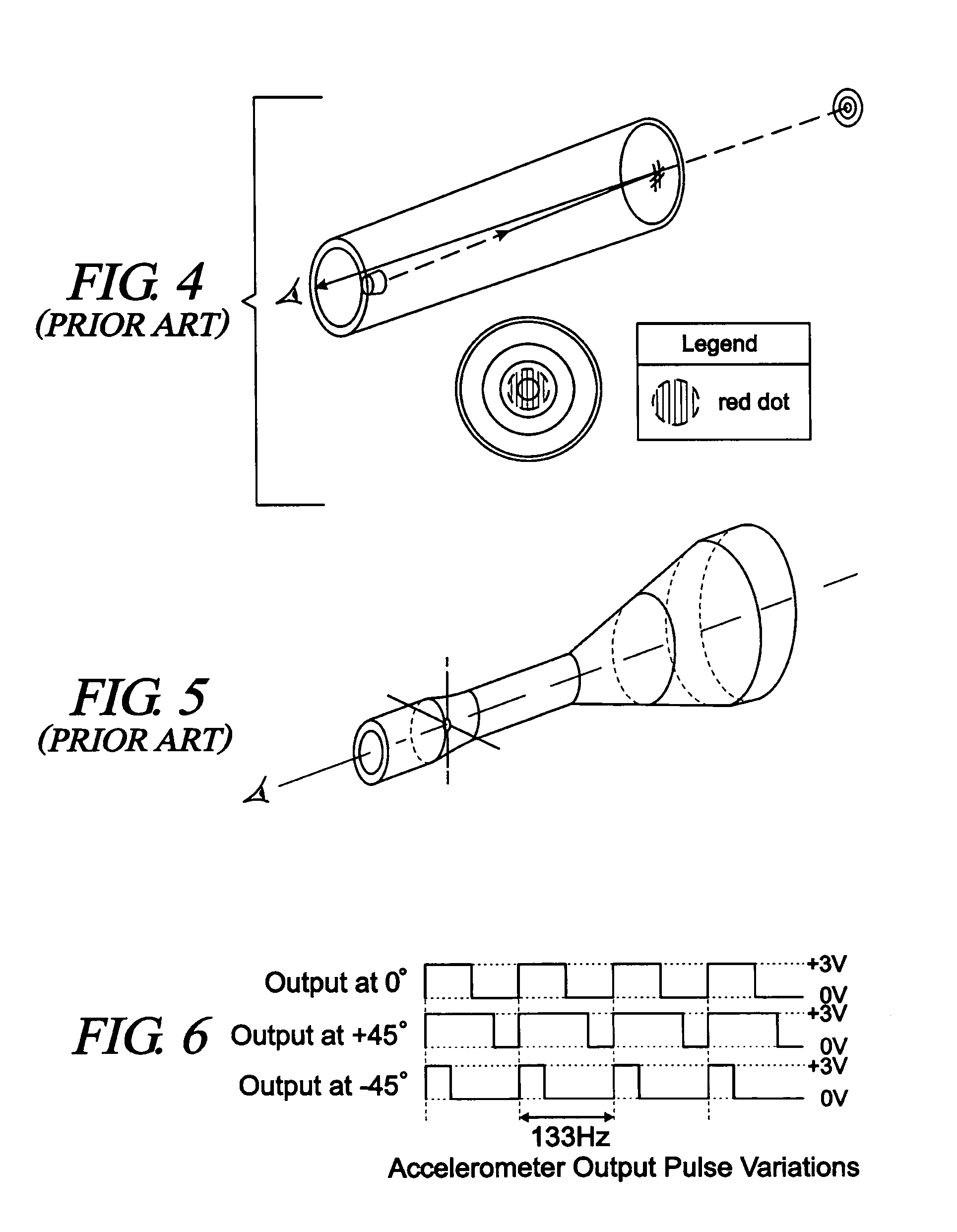
[0038]Referring now to FIG. 7, a schematic block diagram representation of the digital vertical level sensing device of a preferred embodiment of this invention is shown. An electronic accelerometer is shown in communication with a microprocessor. Suitable electronic accelerometers include both analog or digital electronic angle sensors with output signals corresponding to tilt angle, or electronic tilt angle sensing switches (two-state device, with one output for indicating level and another output for indicating non-level). According to the present invention, these accelerometers can be incorporated into devices for measuring and displaying cant angles for projectile launcher applications. In the preferred embodiment of the present invention, a digital electronic accelerometer outputs a continuous signal of digital pulses with a frequency anywhere between 1 Hz–1 MHz. When the accelerometer is parallel to the horizontal plane, corresponding to the conditio...


PUM


Abstract

An electronic vertical angle sensing and indicating device for use on aiming systems is provided for bow sights and for other aiming sights for projectile launchers. Improved vertical level measurement and display minimizes the left-right drift of a projectile by sensing and indicating to the user when the projectile launcher is tilted slightly prior to release of the projectile. The vertical level indicator is easily viewed within the field of direct or near direct vision and focus of the eye in a reduced profile that does not distract the operator from the task of accurately aiming the projectile is provided. One embodiment of the present invention positions the signal indicators in the far-field of view of the eye, so that all of the signal indicators, the sighting means and the distant target being viewed are simultaneously in focus or near-focus.

Description

CROSS-REFERENCES TO RELATED APPLICATIONS[0001]This application is a Non-Provisional Utility application which claims benefit of U.S. Patent Application Ser. No. 60 / 538,015, filed Jan. 21, 2004, now abandoned, entitled “Digital Level Indicator for Improving the Aim of Projectile Launching Devices” which is hereby incorporated by reference.BACKGROUND OF THE INVENTION[0002]The present invention relates generally to electronic angle sensing devices. More particularly, this invention pertains to electronic vertical angle sensing and indicating devices for use on aiming systems associated with projectile launchers.[0003]Archers have relied for many years upon pin sights for aiming their bows. Typically, these pins are adjusted to accurately direct an arrow trajectory toward a target at a specific distance from the archer. Each pin is set for a specific distance, for example, 20, 30, and 40 yards. It is assumed by the archer that, while setting and aligning the pins on his sight, the bow r...

Claims


Application Information

Patent Timeline
Patent Type & Authority Patents(United States)
IPC IPC(8): F41G1/467
CPCF41G1/44F41G1/48F41G1/467
Inventor MURPHY, PATRICK J.JOHNSON, MATTHEW A.MURPHY, MICHAEL C.
Owner MURPHY PATRICK J
Why Eureka
Try Eureka