Inertial drive scanning arrangement and method

a scanning arrangement and inner drive technology, applied in the field of light scanning arrangement, can solve the problems of limiting the scan rate, increasing the mass of the oscillatable assembly, and requiring more electrical power

Inactive Publication Date: 2007-11-20
MICROVISION
View PDF8 Cites 17 Cited by
  • Summary
  • Abstract
  • Description
  • Claims
  • Application Information

AI Technical Summary

Benefits of technology

[0014]Another object of this invention is to minimize electrical power consumption of such readers.
[0015]Still another object of this invention is to increase the scan rate of such readers.
[0016]Yet another object of this invention is to provide a low power, high scan rate, arrangement for scanning light in a myriad of applications not limited to reading optical codes, but, by way of non-limiting example, for projecting an image on a display surface, or for capturing an image from a target.FEATURES OF THE INVENTION

Problems solved by technology

This, however, increased the mass of the oscillatable assembly, thereby requiring more electrical power to drive the assembly and limiting the scan rate.
In readers of the hand-held type, wherein electrical power is supplied by on-board batteries, a high electrical power requirement reduces the working lifetime of the batteries.

Method used


Image

  • Inertial drive scanning arrangement and method
  • Inertial drive scanning arrangement and method
  • Inertial drive scanning arrangement and method

Examples


Embodiment Construction

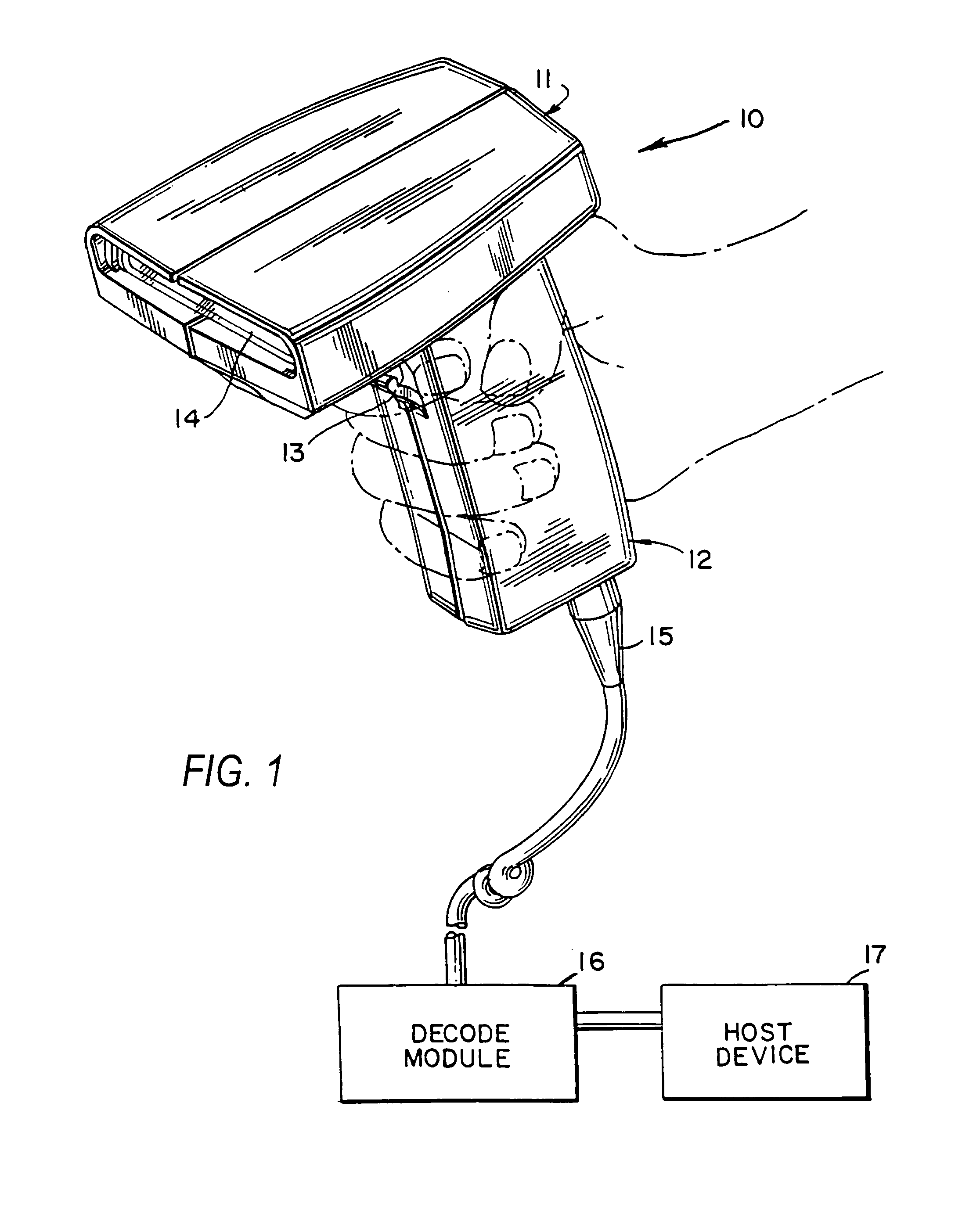
[0035]Referring now to the drawings, reference numeral 10 generally identifies a hand-held, gun-shaped head having a barrel 11 and a handle 12. A manually-operable trigger 13 is situated below the barrel 11 on an upper, forwardly-facing part of the handle 12. As known from the above-identified patents, a light source component, typically, but not necessarily, a laser, is mounted inside the head 10. The light source component emits a light beam along a transmission path which extends outwardly through a window 14 that faces indicia, e.g., bar code symbols, to be read. Also mounted within the head is a photodetector component, e.g., a photodiode, having a field of view, and operative for collecting reflected light returning through the window 14 along a return path from the symbol.

[0036]A scanning component is mounted within the head 10, and is operative for scanning the symbol and / or the field of view of the photodetector. The scanning component typically, but not necessarily, includ...


PUM


Abstract

A light scanning arrangement includes a frame or a base plate directly moved by an inertial drive in order to oscillate a scan element supported by a hinge on the frame at high scan rates and with minimal electrical power consumption.

Description

CROSS-REFERENCE TO RELATED APPLICATION[0001]This application is a continuation-in-part of U.S. patent application Ser. No. 10 / 387,878, filed Mar. 13, 2003, now U.S. Pat. No. 7,182,262.BACKGROUND OF THE INVENTION[0002]1. Field of the Invention[0003]The present invention generally relates to a light scanning arrangement for and method of repetitively scanning targets, for example, optical codes, and, more particularly, to operating such a scanning arrangement under low electrical power conditions to minimize usage of electrical power and at high scan rates.[0004]2. Description of the Related Art[0005]Various optical code readers have been developed heretofore to read optical codes, such as bar code symbols applied to objects in order to identify each object by optically reading the symbol thereon. The bar code symbol itself is a coded pattern comprised of a series of bars of various widths and spaced apart from one another to bound spaces of various widths, the bars and spaces having ...

Claims


Application Information

Patent Timeline
Patent Type & Authority Patents(United States)
IPC IPC(8): G02B5/08G02B26/10G06K7/10
CPCG02B26/0833G06K7/10653G02B26/105
Inventor WOOD, FREDERICK F.YAVID, DMITRIY
Owner MICROVISION
Why Eureka
Try Eureka