Isolated control apparatus incorporating light controlled power semiconductors

a technology of power semiconductors and control apparatuses, applied in electronic switching, pulse techniques, instruments, etc., can solve the problems of the implementation of fbl systems, and the inability to control the power semiconductor devices. , to achieve the effect of reducing the cost of hardwar

Inactive Publication Date: 2007-11-20
BAE SYST INFORMATION & ELECTRONICS SYST INTERGRATION INC
View PDF4 Cites 32 Cited by
  • Summary
  • Abstract
  • Description
  • Claims
  • Application Information

AI Technical Summary

Problems solved by technology

These so called “Fly-By-Wire” (FBW) systems provide many advantages over conventional hydraulic control systems, including substantial reductions in vehicle weight and complexity, but can still be susceptible to problems associated with electro magnetic interference (EMI).
The major technological hurdles in implementation of a FBL system are concentrated at the terminal points of the optical system.
The mere triggering of these devices, however, requires hundreds of Watts.
Thus, the transition from the optical world to the electrical world is fundamentally mismatched and is performed in circuitous fashion resulting in expensive and inherently sensitive hardware, namely, optical control of semiconductors is conventional performed only indirectly through an optical to electrical interface which then controls the power semiconductor.
Thus, conventional optical communication systems still require low power sensitive components to be present in the harsh environment in order to convert the weak optical signal into an electrical signal strong enough to trigger the power semiconductors.

Method used


Image

  • Isolated control apparatus incorporating light controlled power semiconductors
  • Isolated control apparatus incorporating light controlled power semiconductors
  • Isolated control apparatus incorporating light controlled power semiconductors

Examples


Embodiment Construction

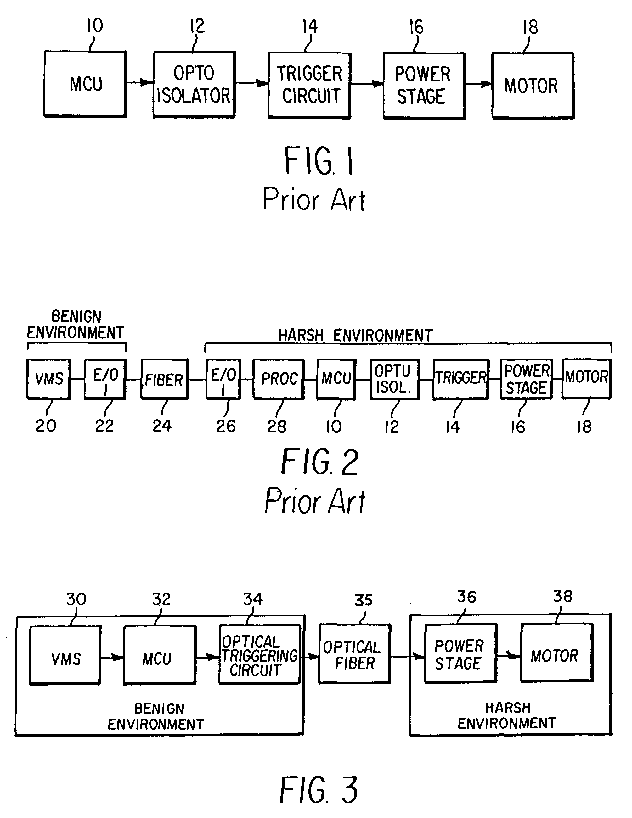
[0021]A typical flight control motor circuit block diagram is illustrated in FIG. 1. A Motor Control Unit (MCU) 10 establishes the servo loop closure and drive logic for motor current commutation and full four-quadrant control. The Motor Control Unit (MCU) 10 is coupled by a conventional opto-isolator 12 to a trigger circuit 14. The trigger circuit 14 is in turn coupled to a power stage drive circuit 16 used to drive a DC motor 18. In operation, the MCU 10 transmits an electrical command signal to the opto-isolator 12, which converts the electrical command signal into a low power optical signal that is supplied to the trigger circuit 14. The trigger circuit 14 converts the low power optical signal received from the opto-isolator 12 into an electrical signal which then triggers the power stage drive circuit 16 to control the operation of the motor 18. In this architecture, the use of the opto-isolator 12 protects the MCU 10 from the high voltage associated with the trigger circuit 14...


PUM


Abstract

A system for direct optical control of electronic power semiconductors includes an optical triggering circuit at a first location, wherein said optical triggering circuit generates an optical trigger signal, a power circuit located at a second location remote from the first location, wherein said power circuit includes a photoconductor that is responsive to the optical trigger signal generated by the optical triggering circuit, and an optical cable coupling the optical triggering circuit to the power circuit. In operation, the power circuit is directly driven by the transmission of the optical trigger signal from the optical triggering circuit to the power circuit via the optical cable.

Description

FIELD OF THE INVENTION[0001]The invention relates in general to control of power semiconductor devices. More specifically, the invention relates to an apparatus for controlling power semiconductor devices wherein optical isolation is provided between a benign environment containing control processing circuitry and a harsh environment containing the power semiconductor devices and a driven load.BACKGROUND OF THE INVENTION[0002]It is desirable in many control applications to remove sensitive electronics from a harsh environment in which a power semiconductor and a driven load are located. Power semiconductors, for example, are used to control heavy machinery motors, robotics, flight actuators and other devices that are usually located in harsh environments having high temperatures, radiation and vibration. While existing power semiconductors (Thyristors, GTO's, IGBT's, etc.) can tolerate temperatures in excess of 100° C., information processing electronics, such as microprocessors, re...

Claims


Application Information

Patent Timeline
Patent Type & Authority Patents(United States)
IPC IPC(8): G06K7/10
CPCH03K17/78H03K17/6871H03K17/14H03K17/567
Inventor ZUCKER, OVED SHLOMO FRANK
Owner BAE SYST INFORMATION & ELECTRONICS SYST INTERGRATION INC
Why Eureka
Try Eureka