
Coaxial cable connector with improved weather seal

a technology of weather sealing and coaxial cable, which is applied in the direction of coupling device connection, two-part coupling device, electrical apparatus, etc., can solve the problems of undesirable additional cost, high inconvenience for installation technicians, and non-hermetic seal

Active Publication Date: 2007-11-20
NANOMATERIALS INT CORP +1
View PDF19 Cites 44 Cited by
  • Summary
  • Abstract
  • Description
  • Claims
  • Application Information

AI Technical Summary

Benefits of technology

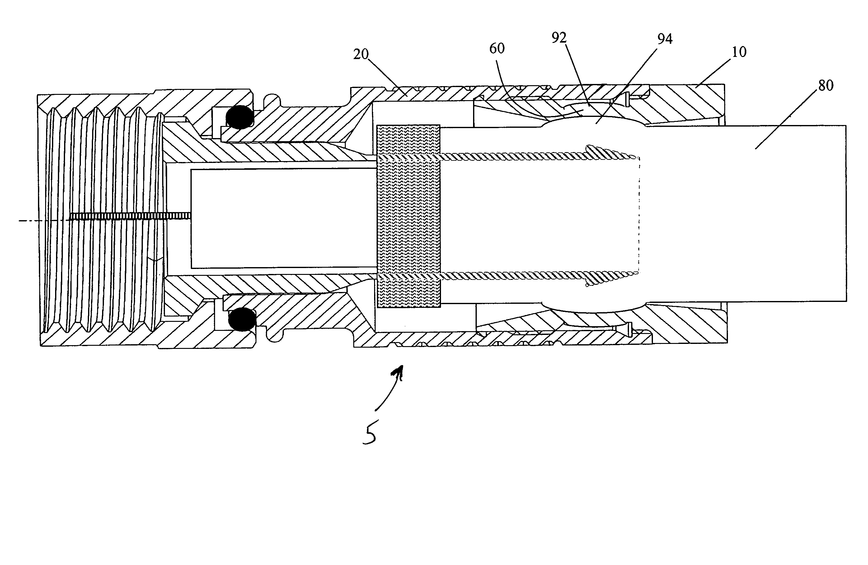
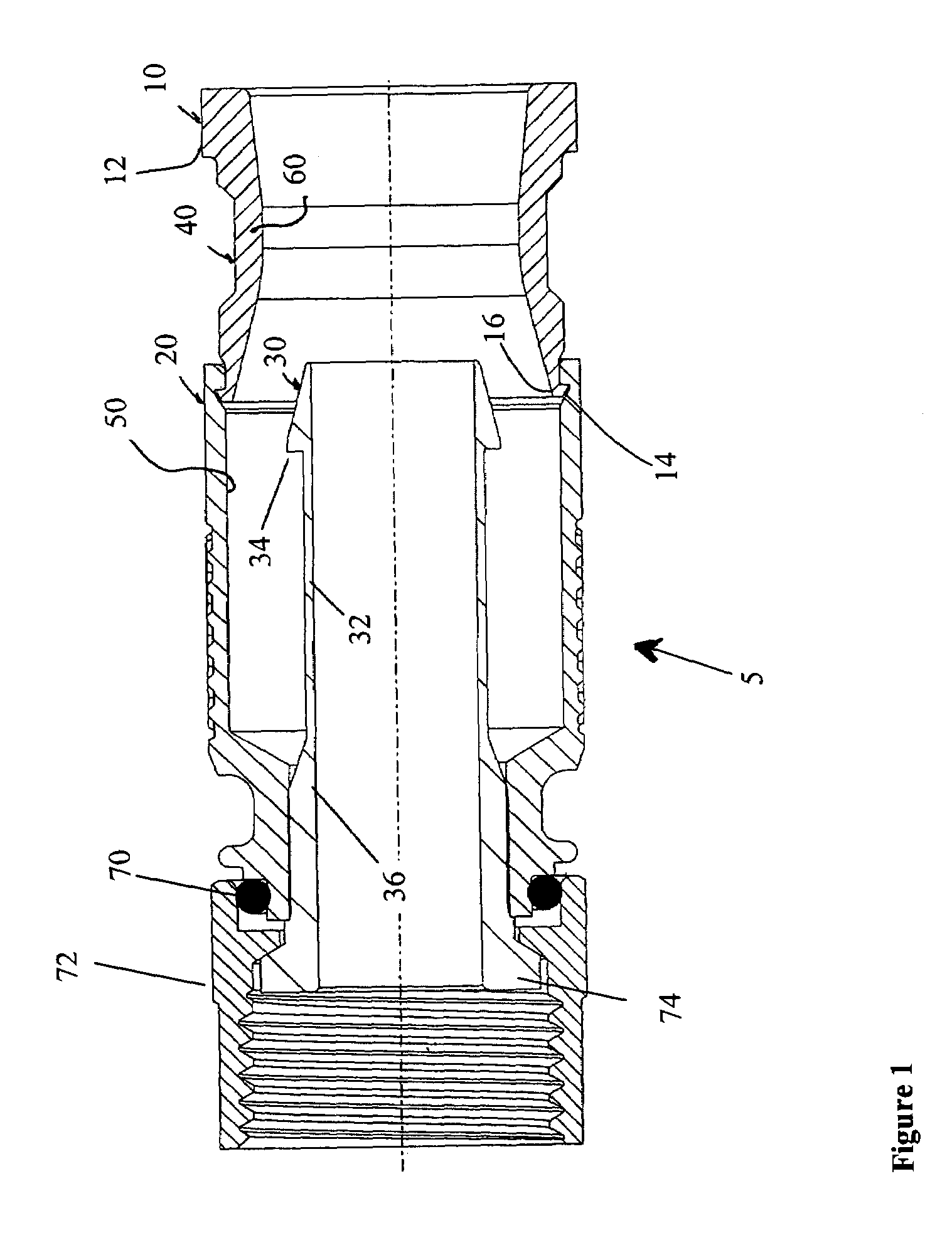
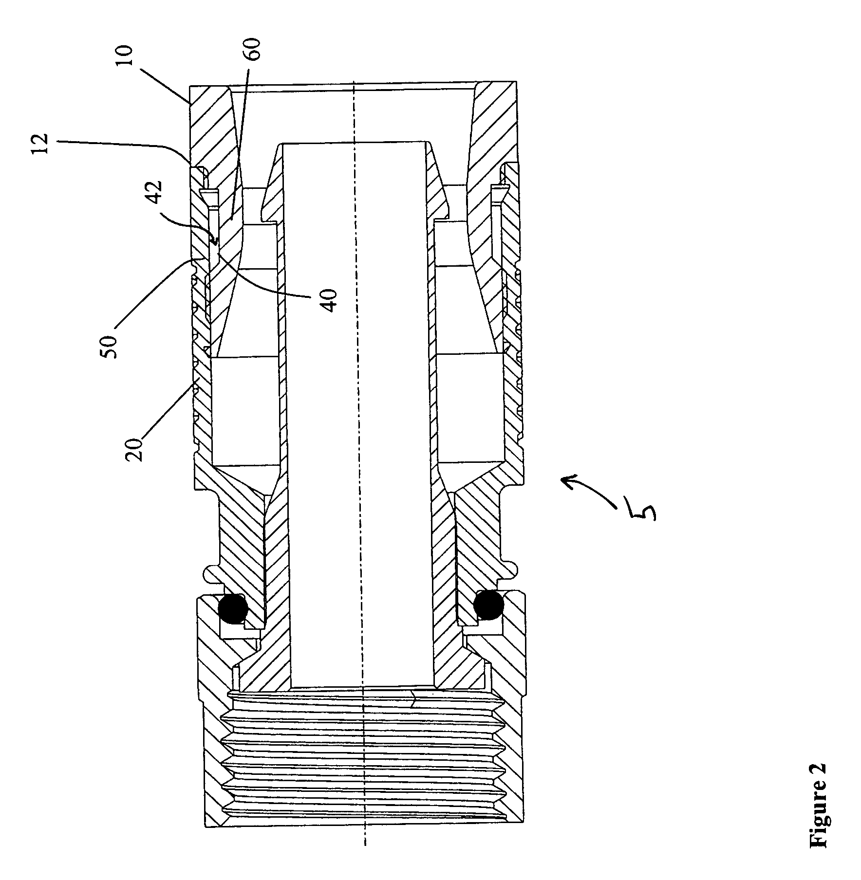
The patent describes a coaxial cable connector that includes a compression ring that provides a weather seal for a wide range of coaxial cable diameter sizes. The compression ring has a flexing portion with a recessed section that flexes outwardly when in contact with a wide diameter coaxial cable. This results in a seal in all cases, regardless of the size of the cable. The connector includes a main body, a compression ring, and a flexible wall area between the compression ring and the main body. The compression ring can flex outwardly when a coaxial cable is inserted into the connector, ensuring a secure and effective seal. The method of manufacturing the connector involves making the main body, adding a threaded nut body to one end, adding a compression ring to the other end, and forming an annular groove in the outer portion of the compression ring to create a flexible wall area. This results in a reliable and effective seal for coaxial cables of various diameters.

Problems solved by technology

This presents a challenge for connector manufacturers because the connectors must provide a watertight seal when installed on the cable.
This presents another problem because the connectors must be properly matched to the cable in order to ensure a proper seal.
This situation is highly inconvenient for installation technicians, representing an undesirable additional cost due to the necessity of holding an extensive inventory of connectors which needs to be maintained, the increased possibility of erroneous mixing-up of connectors of different sizes, and the likelihood of installation mistakes.
Due to the above factors, the critical step of sealing the connection is often not achieved causing a non-hermetic seal and thereby a leak between the cable and the connector.
The signal quality is then compromised at the subscriber's location due to parasite electrical pathways between the center conductor and the shielding formed by moisture, as well as the oxidation and corrosion of the internal connector components and of the center conductor, with consequent deterioration of the quality of the connection.
However, these connectors were not able to address both tight weather seal requirements and the suitability of one connector for use on cables of different sizes.
The complexity of design and number of required parts makes some of these connectors impractical and expensive to manufacture.
In addition, the procedures required to assemble these connectors in the field, often in inclement weather conditions, are complicated.

Method used


Image

  • Coaxial cable connector with improved weather seal
  • Coaxial cable connector with improved weather seal
  • Coaxial cable connector with improved weather seal

Examples


Embodiment Construction

[0019]Referring to FIG. 1, a connector 5 according to an embodiment of the present invention is shown prior to the insertion of a coaxial cable 80 (FIG. 3). Connector 5 includes a main body 20, a compression ring 10 connected to main body 20, a threaded nut 72 for interconnecting connector 20 to a mating connector or port (not shown), an O-ring or gasket 70 which seals the connection between nut 72 and main body 20, and an internal post 36. Internal post 36, nut 72, and O-ring 70 are of conventional construction for use in this type of coaxial cable connector. O-ring 70 is preferably made of easily compressible sealing material, such as rubber, plastic, or similar gasket material. Internal post 36 preferably includes an integrally formed flange 74 and a stem 32. Stem 32 is preferably terminated with a tapered end 30 which preferably also includes a barb 34. The diameter of barb 34 is enlarged compared to the diameter of stem 32. Internal post 36 preferably has a bore of a diameter s...


PUM


Abstract

A coaxial cable connector includes an internal compression ring that provides a weather seal for a wide range of coaxial cable diameter sizes. The compression ring includes a flexing portion with a defined recessed section designed to flex outwardly when in contact with a wide diameter coaxial cable. With larger cables, the wall flexes more, while with smaller cables the wall flexes less, if at all, providing a seal in all cases.

Description

FIELD OF THE INVENTION[0001]This invention relates generally to a connector for terminating a coaxial cable. More specifically, the present invention relates to a coaxial cable connector with an internal compression ring structure that provides a weather seal for a wide range of coaxial cable diameter sizes.BACKGROUND OF THE INVENTION[0002]A number of connectors are available to terminate a coaxial cable so as to connect the cable to various electronic devices, such as switches, distribution boxes, manifolds, and electronic devices. In a typical coaxial cable network, a “drop” cable is used to carry the signal, which may include analog or digital TV signal, internet signal, security monitoring signal, etc., from the rigid coaxial cable near the road to the end user's home. The connector in many cases has to be installed outside of the end user's home so that the servicing and installation personnel can perform troubleshooting as well as connecting and disconnecting the signal withou...

Claims


Application Information

Patent Timeline
Patent Type & Authority Patents(United States)
IPC IPC(8): H01R9/05
CPCH01R13/5205H01R9/0527H01R2103/00H01R24/40
Inventor CHAWGO, SHAWN
Owner NANOMATERIALS INT CORP
Learn More