
Electronic pedometer

a pedometer and electronic technology, applied in the field of pedometers, can solve the problems of inability to distinguish the acceleration of a walk, the number of steps cannot be precisely measured, and the walk cycle is not usually maintained in a fixed sta

Active Publication Date: 2007-11-20
SEIKO INSTR INC
View PDF8 Cites 43 Cited by
  • Summary
  • Abstract
  • Description
  • Claims
  • Application Information

AI Technical Summary

Benefits of technology

The present invention provides an electronic pedometer with a walk sensor that detects a user's steps and outputs a signal for each step. The electronic pedometer uses a counting system to count the number of steps based on the signals from the walk sensor. The counting system counts each signal within a specific range of signals as one step. When a predetermined number of signals within a second range of signals are outputted, the counting system counts the predetermined number of signals as a predetermined number of steps. The electronic pedometer may also have a reference cycle calculating system that averages the cycles of a predetermined number of signals to obtain a moving average. This moving average is used as a reference to determine the number of steps taken by the user. The electronic pedometer may also have a timing function and may be mounted on the user's arm.

Problems solved by technology

However, a problem arises in that various noises due to motions of daily life other than a walk are detected, and hence the number of steps cannot be precisely measured as has been pointed out formerly.
Thus, it is impossible to distinguish the acceleration by a walk from the acceleration (caused by an office work for example) which regularly continues to enter the walk.
However, even if such measures are taken, a walk cycle is not usually maintained in a fixed state.
Hence, it is actually difficult in many cases to detect precisely a cycle.
However, a walk cycle is not usually maintained in a fixed state.
Hence, it is actually difficult in many cases to detect precisely a cycle.
Moreover, even if a dead zone time period is provided, precision in measurement of the number of steps is low.

Method used


Image

  • Electronic pedometer
  • Electronic pedometer
  • Electronic pedometer

Examples


Embodiment Construction

[0034]An electronic pedometer according to an embodiment mode of the present invention will hereinafter be described with reference to the drawings.

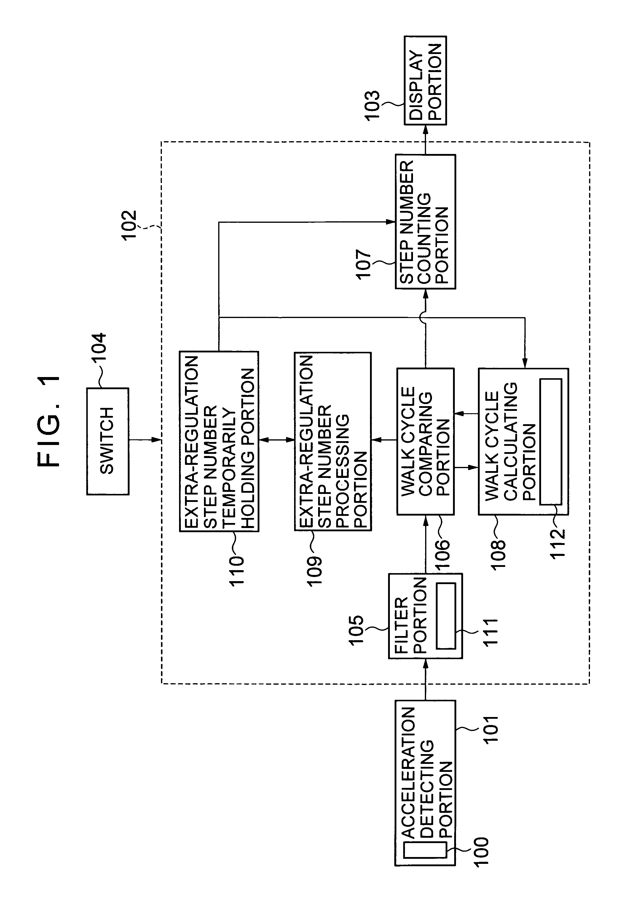
[0035]FIG. 1 is a block diagram of an electronic pedometer according to an embodiment mode of the present invention.

[0036]In FIG. 1, the electronic pedometer includes: an acceleration detecting portion 101 which has a walk sensor 100 constituted by an acceleration sensor and which serves to detect a walk (including running) of a user by the walk sensor 100 to output a signal (walk signal) corresponding to the walk; a counting portion 102 for counting the number of steps of the user based on the walk signal from the acceleration detecting portion 101; a display portion 103 which is constituted by a liquid crystal display device and which serves to display thereon data on the number of steps of the user counted by the counting portion 102; and a switch 104 as manipulation means for carrying out manipulations such as a counting start manipu...


PUM


Abstract

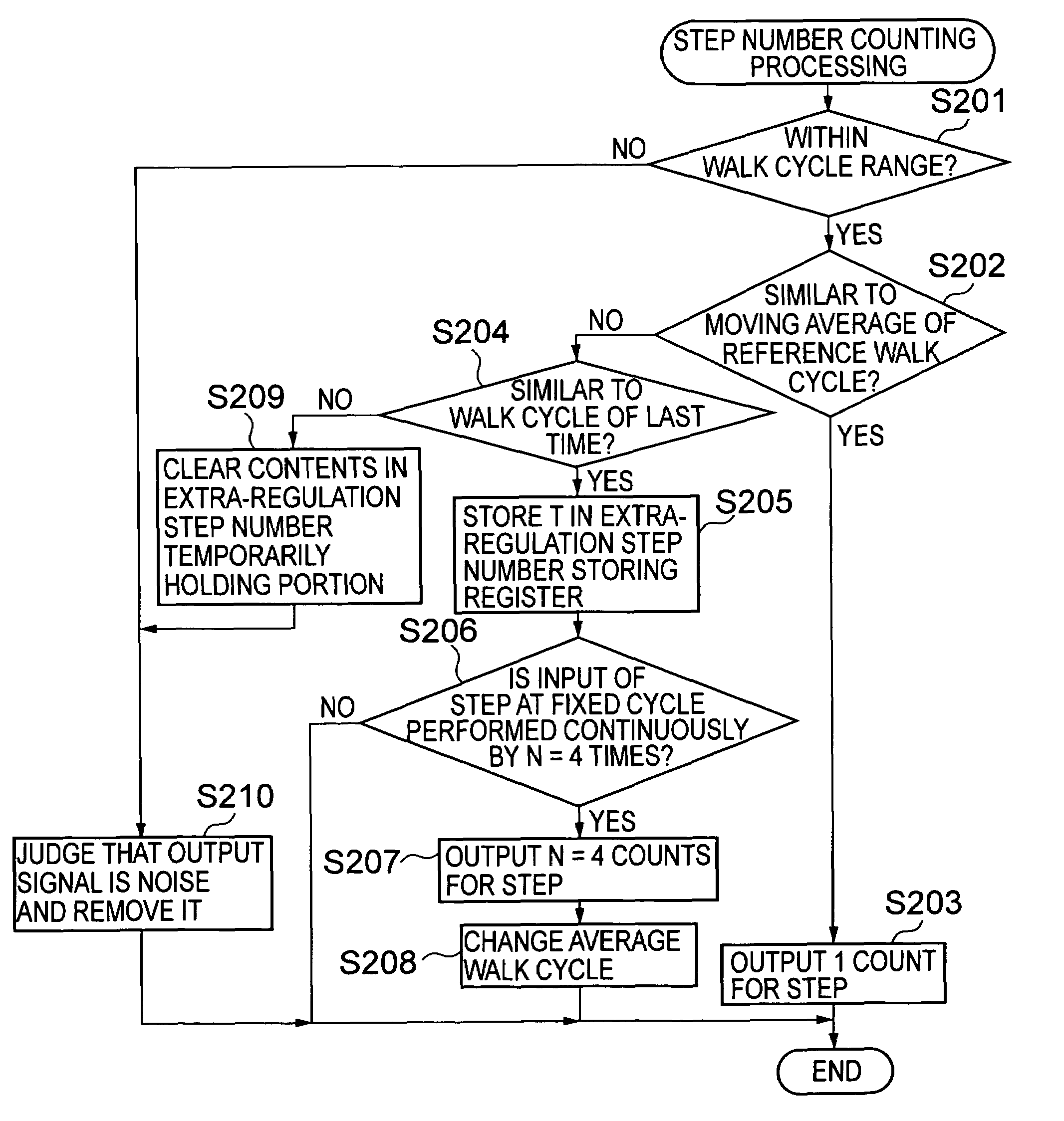
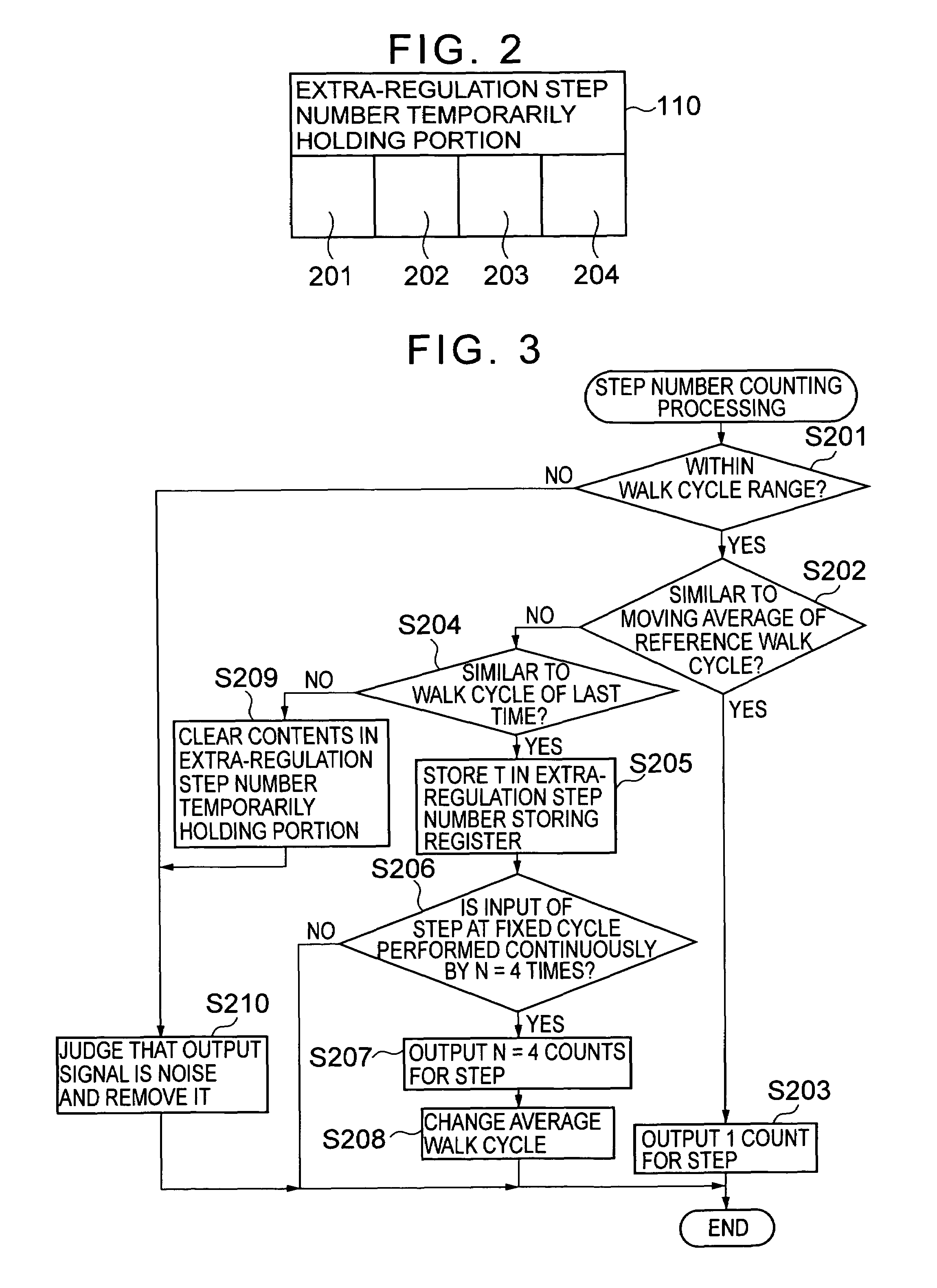
To enhance precision in measurement of the number of steps even when a walk cycle changes. An acceleration detecting portion outputs a walk signal corresponding to a walk of a user detected by a walk sensor. A step number counting portion of a counting portion counts each signal which is judged to be beyond a first reference cycle range by a walk cycle comparing portion among signals from the acceleration detecting portion as the number of steps for one step, and when an extra-regulation step number processing portion judges that a predetermined number of signals each within a second reference cycle range among the signals each beyond the first reference cycle range is continuously outputted, counts the predetermined number of signals as the predetermined number of steps.

Description

BACKGROUND OF THE INVENTION[0001]1. Field of the Invention[0002]The present invention relates to an electronic pedometer which is used by being mounted on a human body in order to electronically count the number of steps by a person having the electronic pedometer mounted thereon.[0003]2. Description of the Prior Art[0004]Heretofore, an electronic pedometer has been developed which is used by being mounted on a human body in order to count the number of steps by a user through an electronic processing.[0005]In general, for counting of the number of steps, an acceleration caused by vertical movement of a user's body during walking is detected to count how many times the accelerations occur as the number of steps.[0006]However, a problem arises in that various noises due to motions of daily life other than a walk are detected, and hence the number of steps cannot be precisely measured as has been pointed out formerly.[0007]In order to solve this problem, there have been proposed a met...

Claims


Application Information

Patent Timeline
Patent Type & Authority Patents(United States)
IPC IPC(8): A63B21/00A63B22/00G01C21/00G01C22/00G06M3/00G06M7/00
CPCG01C22/006Y10S482/90
Inventor TSUJI, TOMOHARU
Owner SEIKO INSTR INC
Learn More