Imaging device with focus switching means for day and night vision

a technology of day and night vision and imaging device, which is applied in the direction of optical radiation measurement, instruments, tubes with screens, etc., can solve the problems of cumbersome and relatively heavy, low interest in using the observation device, and the drawbacks of preceding devices

Active Publication Date: 2007-11-20
SAFRAN ELECTRONICS & DEFENSE
View PDF12 Cites 4 Cited by
  • Summary
  • Abstract
  • Description
  • Claims
  • Application Information

AI Technical Summary

Problems solved by technology

The preceding devices have drawbacks however.
They are therefore cumbersome and relatively heavy, due to the presence of the two separate or semi-separate pathways.
Operationally, the use of said observation device is of little interest insofar as image quality is limited by the LI tube and the yield of its conversions.
The use of a LI device in daytime mode does not match that of a conventional daytime pathway (CMOS or CCD).
Prior art observation devices do not permit use of EBCMOS or EBCCD technology for daytime vision in an observation device comprising a single optic pathway, in particular due to the degradation of the photocathode under strong daytime illumination and to the need for refocusing between the daytime beam and night beam.

Method used


Image

  • Imaging device with focus switching means for day and night vision
  • Imaging device with focus switching means for day and night vision
  • Imaging device with focus switching means for day and night vision

Examples


Embodiment Construction

[0045]The invention chiefly comprises an optical device intended to equip a sight on an infantry helmet for example or a weapon.

[0046]The device advantageously permits day and night vision.

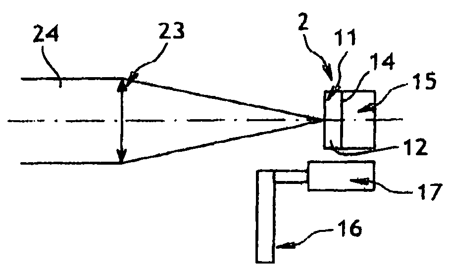
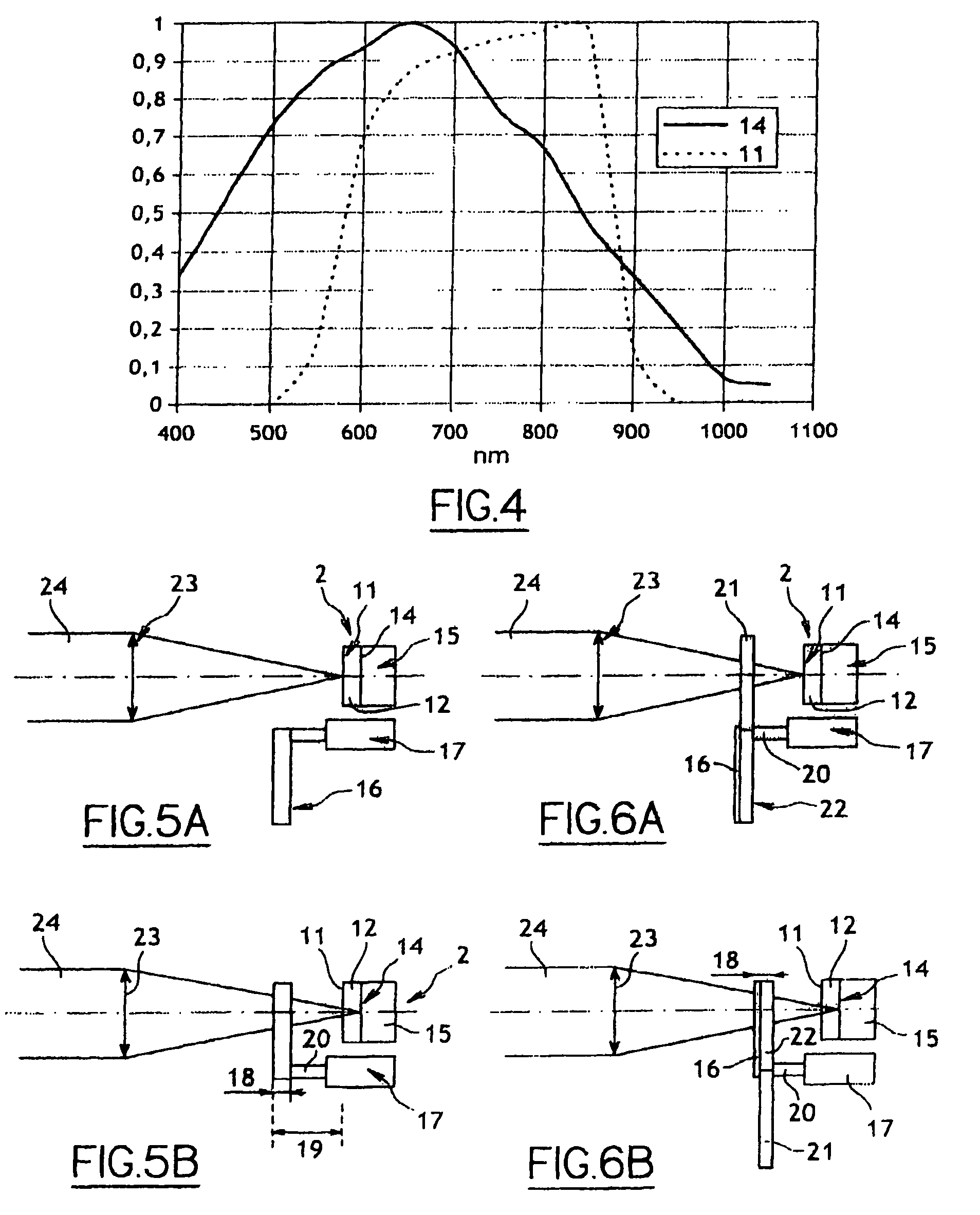
[0047]For this purpose, FIG. 5A shows that an optronic observation device according to the invention, in night observation position, comprises a detector 2 comprising a photocathode 11 and an optic sensor 14. The photocathode 11 is positioned upstream of the sensor 14 on the pathway of a light beam 24 derived from the scene to be observed. The incident light beam 24 is focused by means of a lens 23 on the photocathode 11 of the detector in night position.

[0048]For this purpose, the photocathode 11 conducts a conversion of the photons of beam 24 to covert them into electrons able to be detected by the sensor 14. The electrons pass through a chamber 12 between the photocathode 11 and the sensor 14 and come to strike the sensor 14 to give a night image via processing by means 15 at the output of the ...


PUM


Abstract

An optronic observation device including a detector having a photocathode and a sensor arranged to receive an incident light beam. The device also including a switch to position an optical element opposite the detector in the pathway of the incident beam or to retract the optical element and a focusing element to focus an incident ray on the photocathode when the optical element is in a retracted position. When the optical element is positioned opposite the detector, it is able to focus the beam on the sensor and to filter the beam spectrally to block all or part of the wavelengths for which the responsiveness of the photocathode is greater than a given threshold.

Description

GENERAL TECHNICAL AREA[0001]The present invention pertains to devices for day and night vision.[0002]More precisely, it concerns an optronic device for day and night vision, in particular a portable device.PRIOR ART[0003]Optronic devices for day and night vision are used in various portable devices for the observation of an environment. The observation devices are installed for example in binoculars and / or the sights of weapons or infantry helmets.[0004]It will be understood that portable observation devices are most preferably of small size and lightweight.[0005]Known optronic observation devices generally comprise an integrated day optic pathway and night optic pathway.[0006]An example of said device may therefore comprise two separate pathways. For a video device, this may then comprise two optic pathways and two separate sensors.[0007]Preferably, the day pathway comprises a known detection matrix of Charge-Coupled Device (CCD) type or a known detection matrix of Complementary Me...

Claims


Application Information

Patent Timeline
Patent Type & Authority Patents(United States)
IPC IPC(8): H01J43/04H01J21/20H01J3/14
CPCG02B23/12H01J31/50H04N5/2254H04N5/33H01J2231/50094H04N23/60
Inventor DELTEL, GEOFFROYFAURE, SYLVAINGUETTIER, DENISPATRY, PHILIPPE
Owner SAFRAN ELECTRONICS & DEFENSE
Why Eureka
Try Eureka