Alignment apparatus, exposure apparatus, and device manufacturing method using exposure apparatus

a technology of exposure apparatus and manufacturing method, which is applied in the direction of photomechanical treatment, instruments, printing, etc., can solve the problems of filter dust, turbulence in refrigerant flow, and inability to adjust the position, so as to improve the accuracy of position measurement and suppress temperature fluctuation. , the effect of high accuracy

Inactive Publication Date: 2007-11-20
CANON KK
View PDF5 Cites 2 Cited by
  • Summary
  • Abstract
  • Description
  • Claims
  • Application Information

AI Technical Summary

Benefits of technology

[0006]The present invention has been made in view of the above problems, and has as its object to provide a technique which suppresses the temperature fluctuation or the like of a measurement optical path to improve position measurement accuracy, thereby performing highly accurate exposure.
[0009]According to the present invention, temperature fluctuation or the like of the optical path of measurement light can be suppressed to improve the position measurement accuracy.

Problems solved by technology

If the flow rate of the refrigerant increases, the flow of the refrigerant may induce the vibration of the pipe or the like.
This is because when the flow rate of the refrigerant increases, the flow of the refrigerant becomes turbulence.
As described above, when temperature-controlled gas is supplied to a space where measurement light is guided, if the flow rate of the gas increases, the filter may produce dust.
If the flow rate exceeds the regulated velocity, the filter produces dust.
Even when no filter is used, if the flow rate of the gas is increased, it induces vibration of the pipe or the like employed to circulate the gas.

Method used


Image

  • Alignment apparatus, exposure apparatus, and device manufacturing method using exposure apparatus
  • Alignment apparatus, exposure apparatus, and device manufacturing method using exposure apparatus
  • Alignment apparatus, exposure apparatus, and device manufacturing method using exposure apparatus

Examples


first embodiment

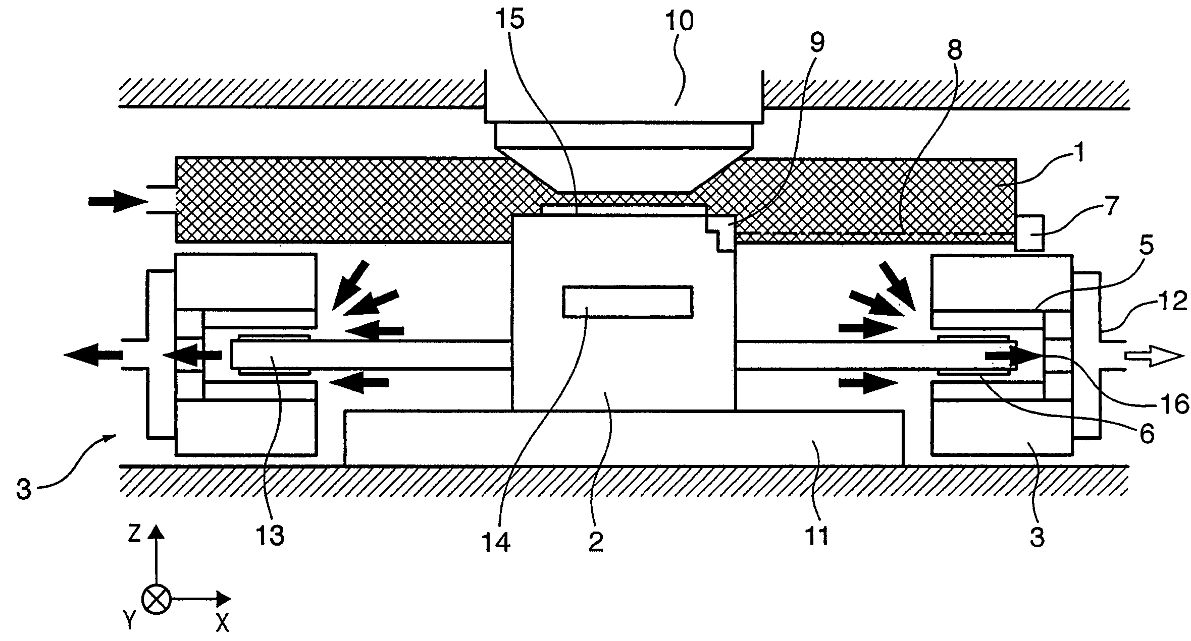
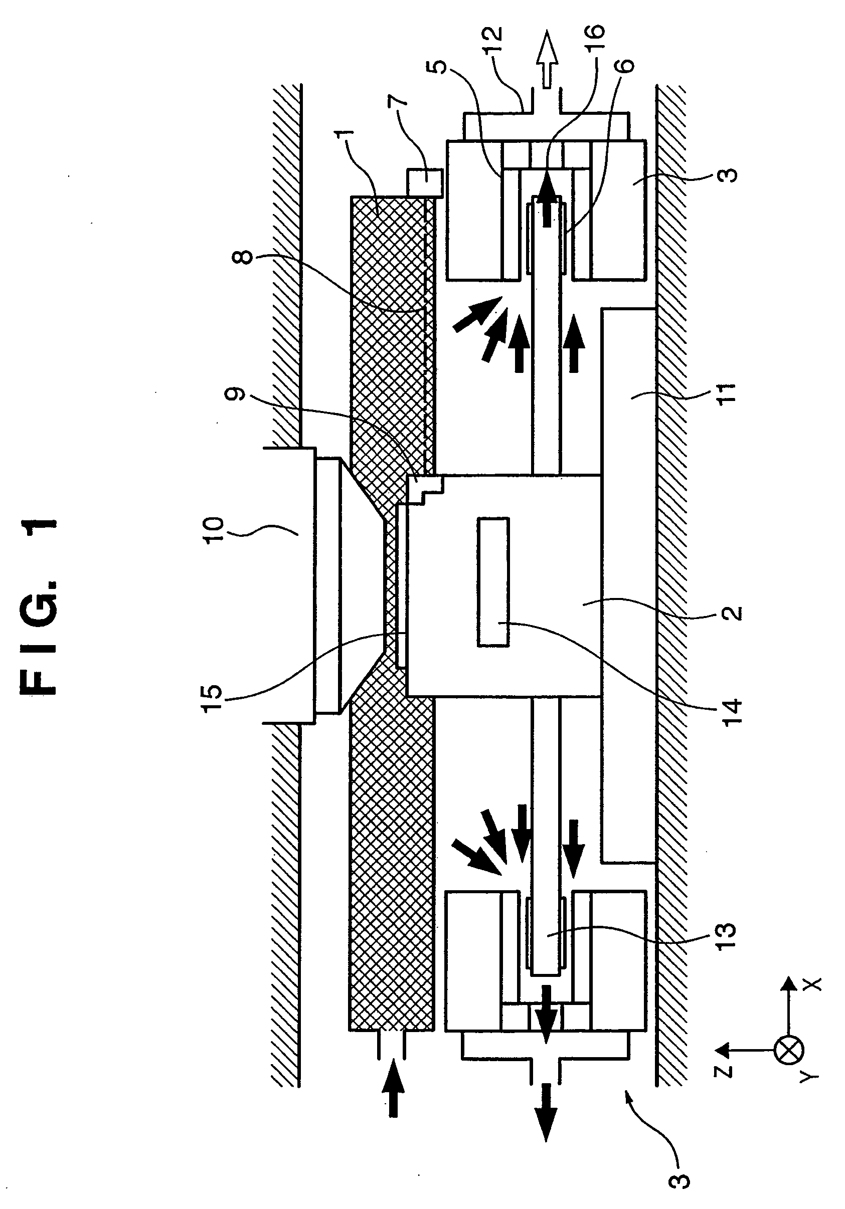
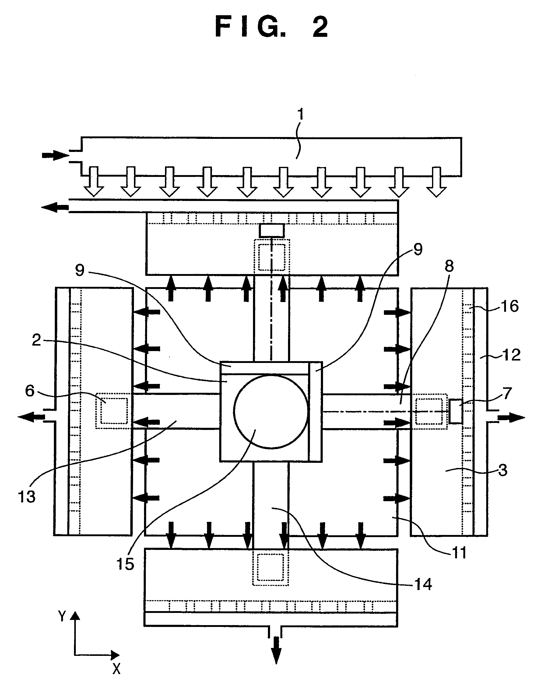
[0020]FIG. 1 is a view showing the schematic arrangement of an exposure stage (wafer stage) in an exposure apparatus (device manufacturing apparatus) according to a preferred embodiment of the present invention, and FIG. 2 is a plan view of FIG. 1. Arrows in FIGS. 1 and 2 indicate gas flows.

[0021]A pattern formed on a master or original (not shown) is reduced and projected onto a wafer 15 through a projection optical system 10. As the projection optical system 10, a dioptric optical system comprising only a plurality of optical lens elements, an optical system (catadioptric optical system) having a plurality of optical lens elements and at least one concave mirror, an optical system having a plurality of optical lens elements and at least one diffraction optical element such as a kinoform, an all-mirror-type reflection optical system, or the like can be employed.

[0022]The wafer stage has a movable element 2 on which the wafer 15 is loaded, a Y guide bar 14 which guides the movable e...

second embodiment

[0032]FIG. 3 is a view showing the schematic arrangement of a wafer stage according to the second embodiment of the present invention, and FIG. 4 is a plan view of FIG. 3. The arrows in FIGS. 3 and 4 indicate the flows of gas. Constituent components having the same functions as those of the first embodiment are denoted by the same reference numerals, and a detailed description thereof will be omitted.

[0033]The second embodiment provides an arrangement which does not have a Y guide bar used in the first embodiment. An X guide bar 13 serves as a linear motor. A permanent magnet (not shown) serving as a linear motor movable element is provided to a movable element 2 on which a wafer 15 is loaded. Coils 4a serving as linear motor stators are arranged in the X guide bar 13 in an X direction so as to oppose the permanent magnet. When the coils are energized, the movable element 2 can move in the X direction. Coils may be arranged in the movable element 2 and a permanent magnet may be arra...


PUM


Abstract

An alignment apparatus includes driving means having a movable element and a stator, a measurement unit which measures a position of a moving member moved by the driving means using measurement light, and a discharging unit to discharge gas existing in an optical path of the measurement light. The discharging unit is provided to the stator.

Description

FIELD OF THE INVENTION[0001]The present invention relates to an alignment apparatus having driving means comprising a movable element and stator, and a laser interferometer to measure the position of a moving member moved by the driving means, an exposure apparatus, and the like.BACKGROUND OF THE INVENTION[0002]In general, the position of a wafer stage or reticle stage provided to an exposure apparatus is measured by a laser interferometer. It is known that the measurement accuracy of the laser interferometer is decreased by the temperature fluctuation (variation) of the optical path of measurement light. In order to suppress the temperature fluctuation, a technique is available which controls the temperature of a refrigerant by circulating the refrigerant in the surface of a heat-generating member arranged in the vicinity of a space where the measurement light is guided, thereby decreasing the temperature fluctuation of the optical path.[0003]A technique is also available which sup...

Claims


Application Information

Patent Timeline
Patent Type & Authority Patents(United States)
IPC IPC(8): G03B27/58
CPCG03F7/70758G03F7/70933G03F7/70858G03F7/70775
Inventor MARUYAMA, HIROYUKI
Owner CANON KK
Why Eureka
Try Eureka