
Method and apparatus for joining adhesive tape

a technology of adhesive tape and joining method, which is applied in the directions of paper hanging, transportation and packaging, packaging, etc., can solve the problems of reducing the sliding ability of the surface, and affecting the adhesion effect of the adhesive tape, so as to prevent any generation of creases, facilitate movement, and improve the adhesion

Inactive Publication Date: 2007-11-27
NITTO DENKO CORP
View PDF9 Cites 6 Cited by
  • Summary
  • Abstract
  • Description
  • Claims
  • Application Information

AI Technical Summary

Benefits of technology

The present invention provides an adhesive tape joining method and apparatus that can smoothly and easily join an adhesive tape to a curved surface without creating a crease on the tape. The method involves guiding and supplying the adhesive tape to the joining roller while moving the joining roller along the workpiece in a predetermined posture. The apparatus includes a traveling and guiding first guide roller, posture holding guide rollers, a joining roller, a tape supplying roller, and a tape guide. The curved portion of the adhesive tape can pass through the curved portion by releasing one end in the tape width direction of the tape inserting clearance and forming the tape positioner for receiving and guiding the other side edge of the adhesive tape at the other end of the tape inserting clearance.

Problems solved by technology

However, as described above, a winding starting portion of the adhesive tape around the pressing roller is held between the pressing roller and the tape guide plate, and further, the pressing roller is covered with a rubber-like elastic member, thereby reducing the slidability of the surface and making it difficult to shift the adhesive tape, so that the adhesive tape is turned into a restricted state in which the orientation or position of the adhesive tape is hardly changed.
Consequently, when the curved portion of the adhesive tape is guided at the portion restricted as described above, a side end edge of the tape is strongly pressed or scraped against a positioning surface, and as a result, a crease is liable to be generated on the adhesive tape.

Method used


Image

  • Method and apparatus for joining adhesive tape
  • Method and apparatus for joining adhesive tape
  • Method and apparatus for joining adhesive tape

Examples


Embodiment Construction

[0033]Description will be given below of an adhesive tape joining apparatus in a preferred embodiment according to the present invention in reference to the drawings.

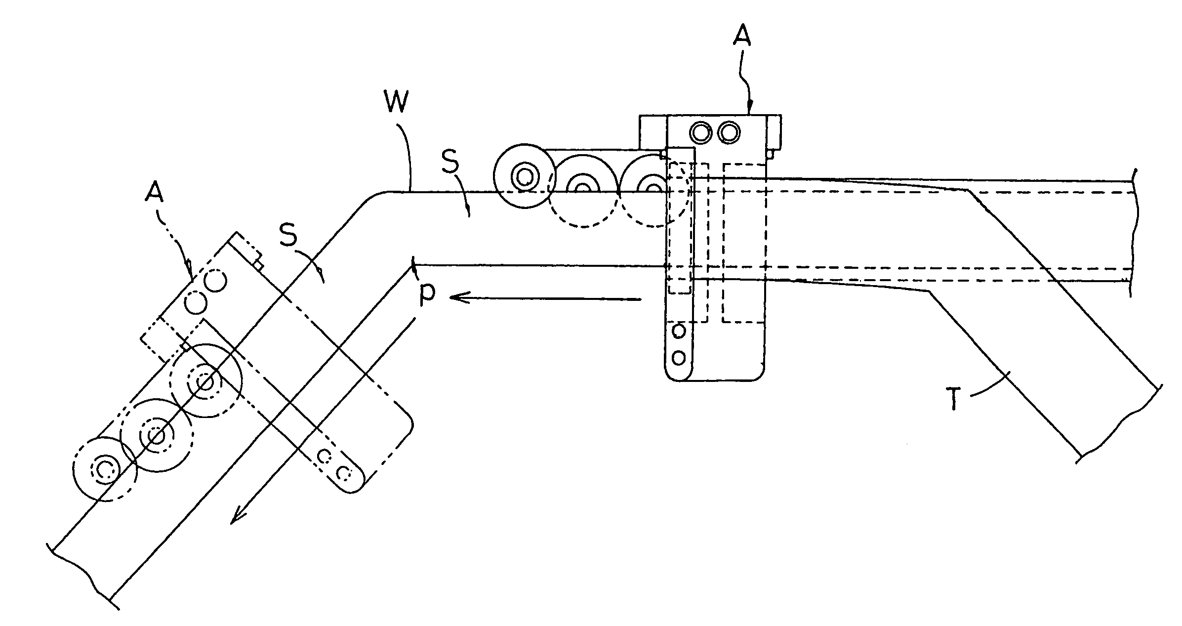
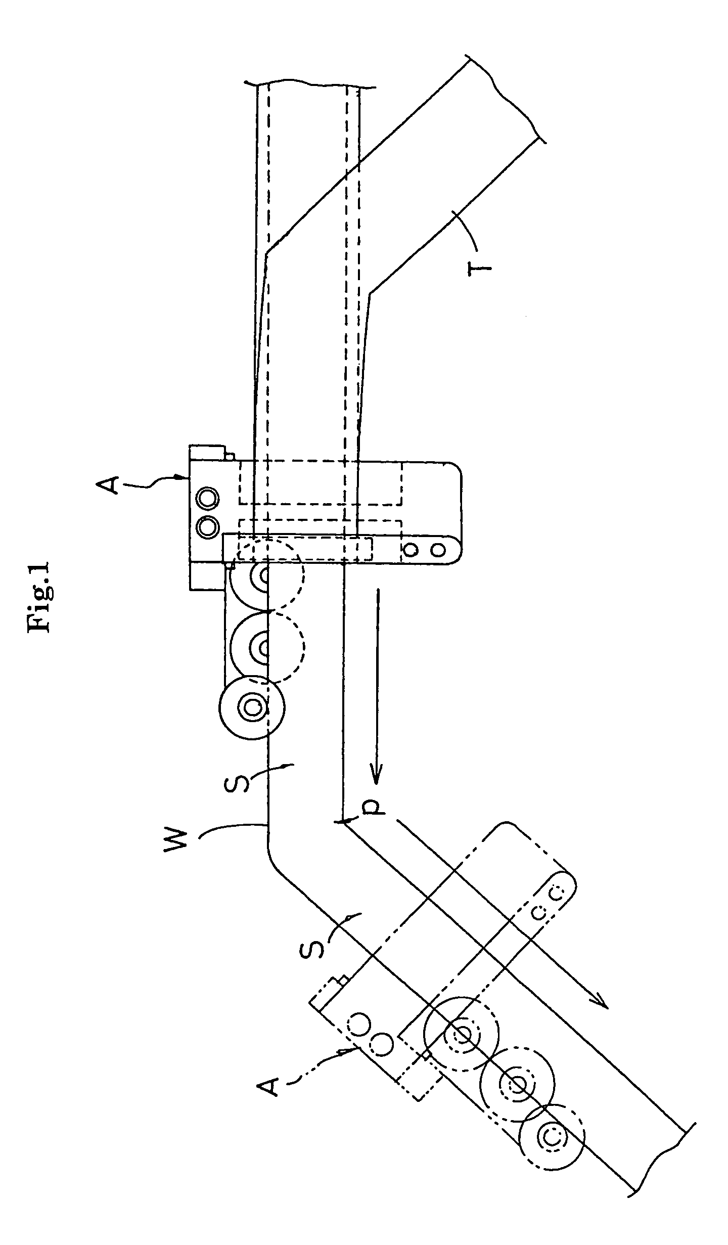
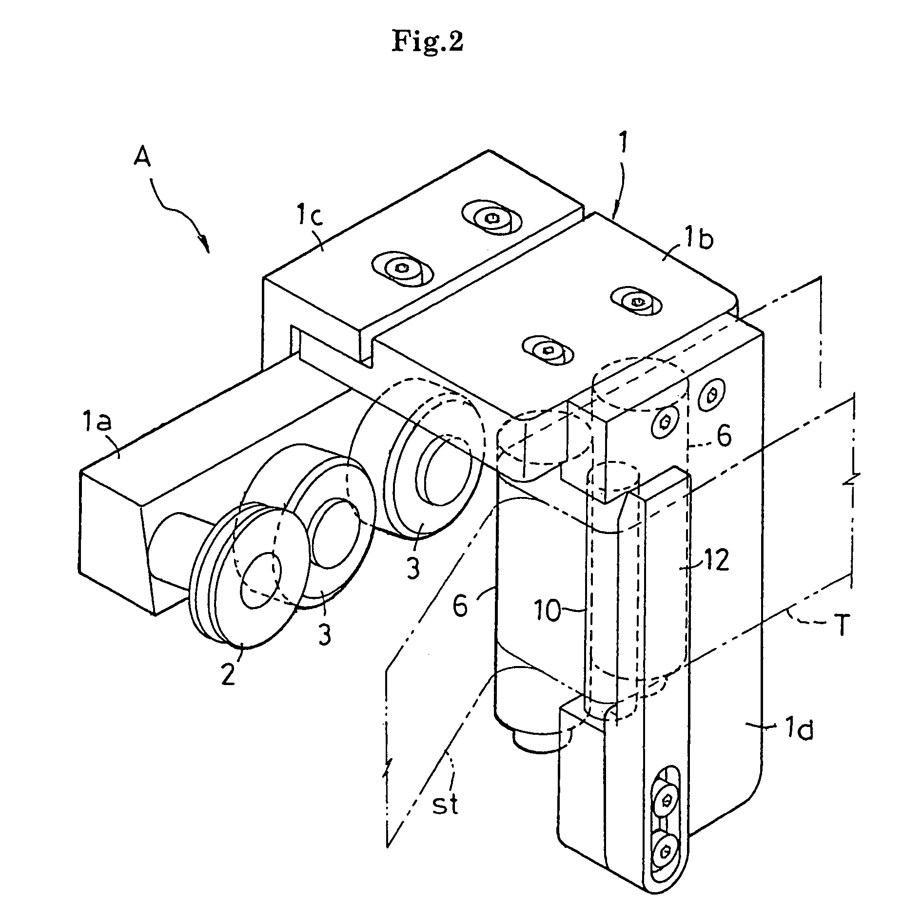
[0034]Here, FIG. 1 is a front view showing a process of joining an adhesive tape T onto a curved workpiece W by the use of an adhesive tape joining apparatus A according to the present invention; FIG. 2 is a perspective view showing the outside appearance of the adhesive tape joining apparatus A; and FIG. 3 is a front view showing the adhesive tape joining apparatus A. The workpiece W in the preferred embodiment is a door sash in an automobile. A black adhesive tape is joined onto a curved side surface of the door sash in place of black coating.

[0035]The workpiece W is obtained by curving a peripheral frame member made of sheet metal having a cross-sectional shape shown in FIG. 6 into a desired shape by welding connection. A window glass inserting groove m1 is formed at the inner circumference, and further, a weather st...


PUM

PropertyMeasurementUnit
elastic pressureaaaaaaaaaa
widthaaaaaaaaaa
adhesiveaaaaaaaaaa

Abstract

An adhesive tape inserted into a tape inserting clearance defined between a tape supplying roller and a tape guide is supplied to joining rollers while being wound around the tape supplying roller under guidance. At the tape inserting clearance, one side edge of the adhesive tape is guided to a tape positioner in slide contact, to be positioned in a tape width direction, and further, the adhesive tape T is inserted and moved while allowing the tape to be moved toward the other side edge of the adhesive tape.

Description

BACKGROUND OF THE INVENTION[0001](1) Field of the Invention[0002]The present invention relates to an adhesive tape joining method, which is used in the case where, for example, an adhesive tape is joined to a curved workpiece such as a door sash in an automobile, and an adhesive tape joining apparatus for use in the method.[0003](2) Description of the Related Art[0004]In recent years, there has been developed a technique of joining a black adhesive tape in place of black coating applied to a door sash in the process of manufacturing an automobile. There has been proposed means for supplying and joining an adhesive tape, which is formed into a curved shape in conformity with a curve of a tape joined surface in a workpiece, to a pressing roller while a joining apparatus is moved along the workpiece under guidance (see, for example, JP-A 2001-328573).[0005]The above-proposed adhesive tape joining apparatus has a feature in that the adhesive tape can be smoothly joined onto the curved w...

Claims


Application Information

Patent Timeline
Patent Type & Authority Patents(United States)
IPC IPC(8): B32B37/00B62D65/00B65H35/07B65H37/00B65H37/04
CPCB65H37/005Y10T156/17Y10T156/1788B65H2801/51
Inventor MORIMOTO, MASAKAZUIKISHIMA, SHINSUKENATSUME, MASAYOSHIISHIGURO, SHIGEKI
Owner NITTO DENKO CORP
Learn More