Mower unit

a mower and unit technology, applied in the field of mower units, can solve the problems of liable side discharge operation, liable low efficiency of discharging grass clippings, liable mulching operation, etc., and achieve the effects of convenient collection of grass clippings, good finish, and low pressure differen

Active Publication Date: 2009-06-09
KUBOTA LTD
View PDF11 Cites 6 Cited by
  • Summary
  • Abstract
  • Description
  • Claims
  • Application Information

AI Technical Summary

Benefits of technology

[0012]Thus, even if winds and grass clippings from each rotary cutting blade deviate from the baffle, the upper baffle portion and lower baffle portion guide the winds and grass clippings to flow toward the rotation region of each rotary cutting blade. Consequently, the winds and grass clippings flow in one rotation region and the other rotation region separately. The winds from one rotary cutting blade easily pass through the air passage to flow into the rotation region of the other rotary cutting blade, to allow the grass clippings from one rotary cutting blade to flow into the rotation region of the other rotary cutting blade. Where no grass discharge opening is provided at one lateral end of the blade housing, there is little chance of pressure difference occurring between the pair of rotation regions. Thus, in spite of the air passage, the winds from each rotary cutting blade, after deviating from the baffle, can easily return to the rotation region of each rotary cutting blade.
[0013]To enable a side discharge operation, grass clippings cut by the rotary cutting blade far from the grass discharge opening are made to join smoothly the grass clippings cut by the rotary cutting blade near the grass discharge opening. Thus, the operation may be carried out conveniently, with the grass clippings from each rotary cutting blade reliably discharged to areas laterally outward of the mower to facilitate collection of the grass clippings. To enable a mulching operation, the grass clippings cut by each rotary cutting blade are circulated in the rotation region of each rotary cutting blade. In this state, the grass clippings are shredded by each rotary cutting blade, and discharged under the mower as uniformly distributed transversely of the mower. Thus, the operation is carried out to produce a good finish.

Problems solved by technology

In this case, when the conventional technique relating to the baffle is employed, the side discharge operation is liable to low efficiency of discharging grass clippings to areas laterally outward of the mower unit, or the mulching operation is liable to low efficiency of shredding and dispersing grass clippings.
Then, in time of side discharge operation, the grass clippings cut by the rotary cutting blade far from the grass discharge opening will have difficulty in flowing into the rotation region of the rotary cutting blade near the grass discharge opening.

Method used


Image

  • Mower unit
  • Mower unit
  • Mower unit

Examples


Embodiment Construction

[0027]An embodiment of this invention will be described hereinafter with reference to the drawings.

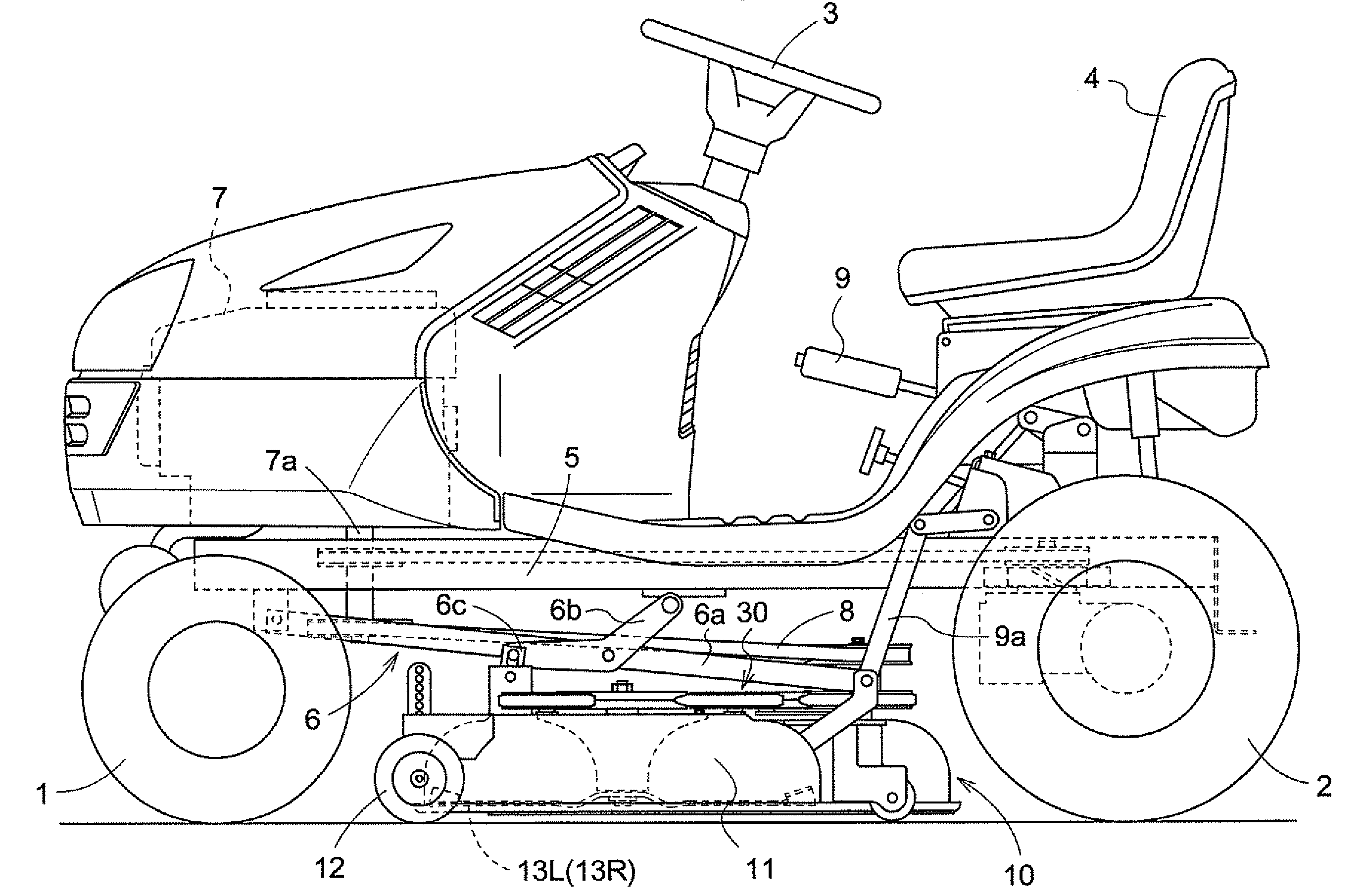
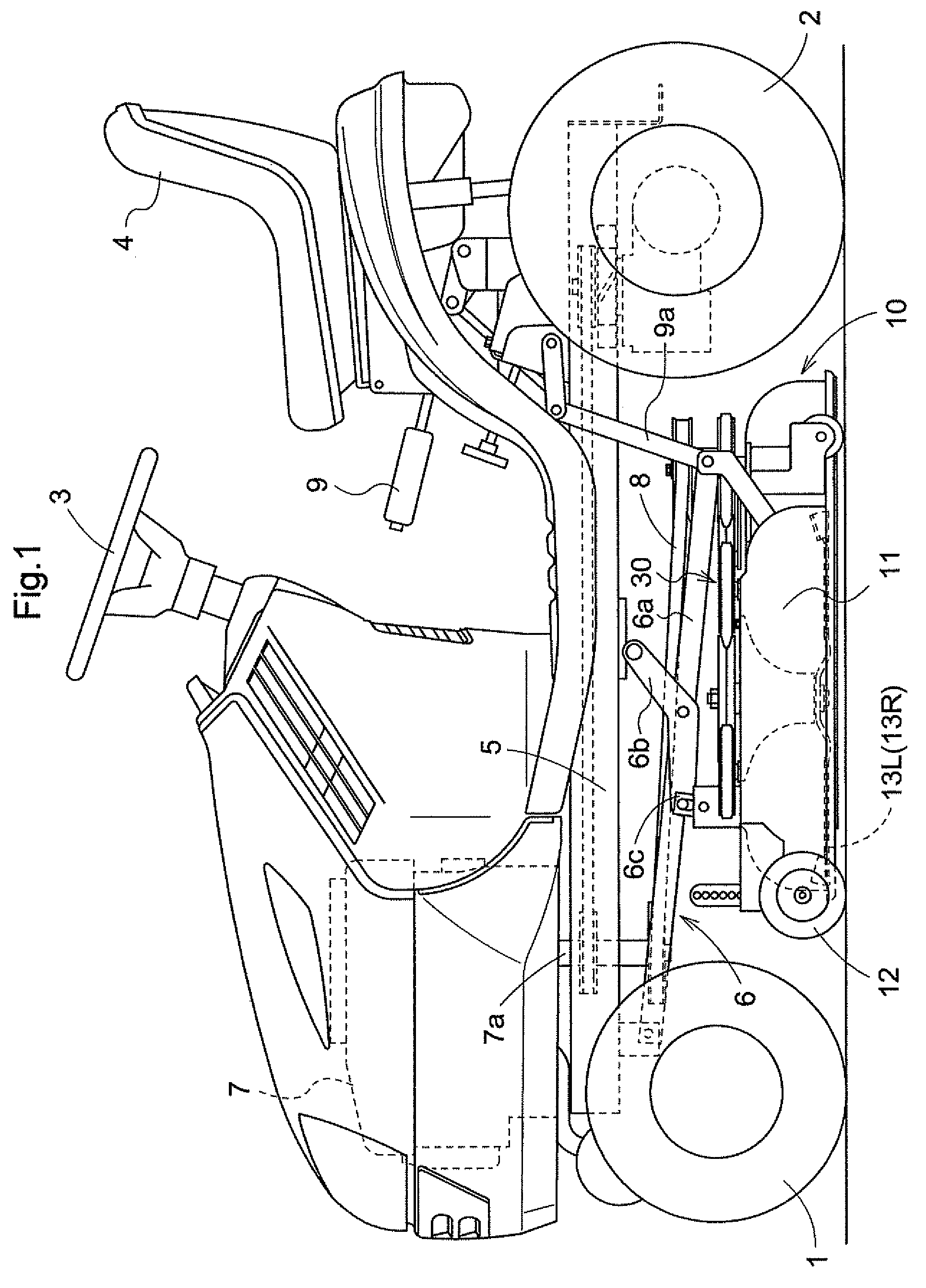
[0028]FIG. 1 shows a side elevation of a riding type grass mower with a mower unit 10 embodying this invention. As seen, the riding type grass mower has a self-propelled vehicle body with a pair of right and left dirigible front wheels 1 and a pair of right and left rear drive wheels 2, and a driving platform including a steering wheel 3 and a driver's seat 4. The mower unit 10 embodying this invention is connected to a body frame 5 of the self-propelled vehicle body between the front and rear wheels through a link mechanism 6. The vehicle body has an engine 7 mounted in a front position thereof. The engine 7 has a vertical output shaft 7a, and its output is transmitted by a transmission belt 8 to a blade drive mechanism 30 of the mower unit 10. The link mechanism 6 includes lift links 6a connected to forward positions of the vehicle body frame 5 and rear end positions of a blade housi...


PUM


Abstract

A mower unit includes a housing, a pair of cutting blades arranged inside the housing, each of the cutting blades being rotatable about a respective vertical axis supported by the housing, the cutting blades being driven to be rotated in opposite directions, and a baffle arranged generally between rotation regions of the cutting blades to guide air flows generated by the cutting blades. The baffle defines an upper baffle portion located adjacent an upper region of the housing, a lower baffle portion located adjacent a lower region of the housing, and an air passage formed for allowing the air flows to flow between the upper baffle portion and lower baffle portion.

Description

BACKGROUND OF THE INVENTION[0001]This invention relates to a mower unit. Such a mower unit has a housing, and a pair of cutting blades arranged in the housing to be rotatable, respectively, about vertical axes supported by the housing. The pair of cutting blades are driven to rotate in opposite directions.[0002]A conventional mower unit as noted above is disclosed in JP 2001-45828, for example. The mower unit shown in this document has three blades arranged transversely in a housing, and a vacuum plate located forwardly of the three blades. Of the three blades, the blade located in the middle and the blade located at right-hand side are driven to rotate in opposite directions. The vacuum plate has a curved discharge portion extending to a region between a rotation region of the middle blade and a rotation region of the right-hand blade. The curved discharge portion serves as a baffle for the middle blade and right-hand blade acting as a pair of rotary cutting blades, to guide winds ...

Claims


Application Information

Patent Timeline
Patent Type & Authority Patents(United States)
IPC IPC(8): A01D67/00
CPCA01D34/667A01D34/81A01D42/005Y10S56/09
Inventor IMANISHI, RYOUZOUMORIKAWA, TOMOYUKIUEMURA, KATSUHIKOYAMASHITA, NOBUYUKIKUROHARA, KAZUAKIOSHIMA, HIROSHI
Owner KUBOTA LTD
Why Eureka
Try Eureka