Optical methods for phase change materials

a phase change material and optical method technology, applied in the field of optical methods for phase change materials, can solve the problems of poor thermal conductivity in their solid state, complex design and hence cost, and the intrinsically more expensive of pcm storage tanks than the commonly used water buffer systems, so as to limit the amount of system redundancy

Active Publication Date: 2020-10-20
VLAAMSE INSTELLING VOOR TECHNOLOGISCH ONDERZOEK NV VITO
View PDF23 Cites 1 Cited by
  • Summary
  • Abstract
  • Description
  • Claims
  • Application Information

AI Technical Summary

Benefits of technology

[0010]An advantage of embodiments of the present invention is being able to measure an average value for the state of a PCM, e.g. the amount of the two phases such as solid and liquid of a PCM inside an entire vessel which allows a State of Charge (SoC) value to be determined quickly without extensive testing of many sensor readings.
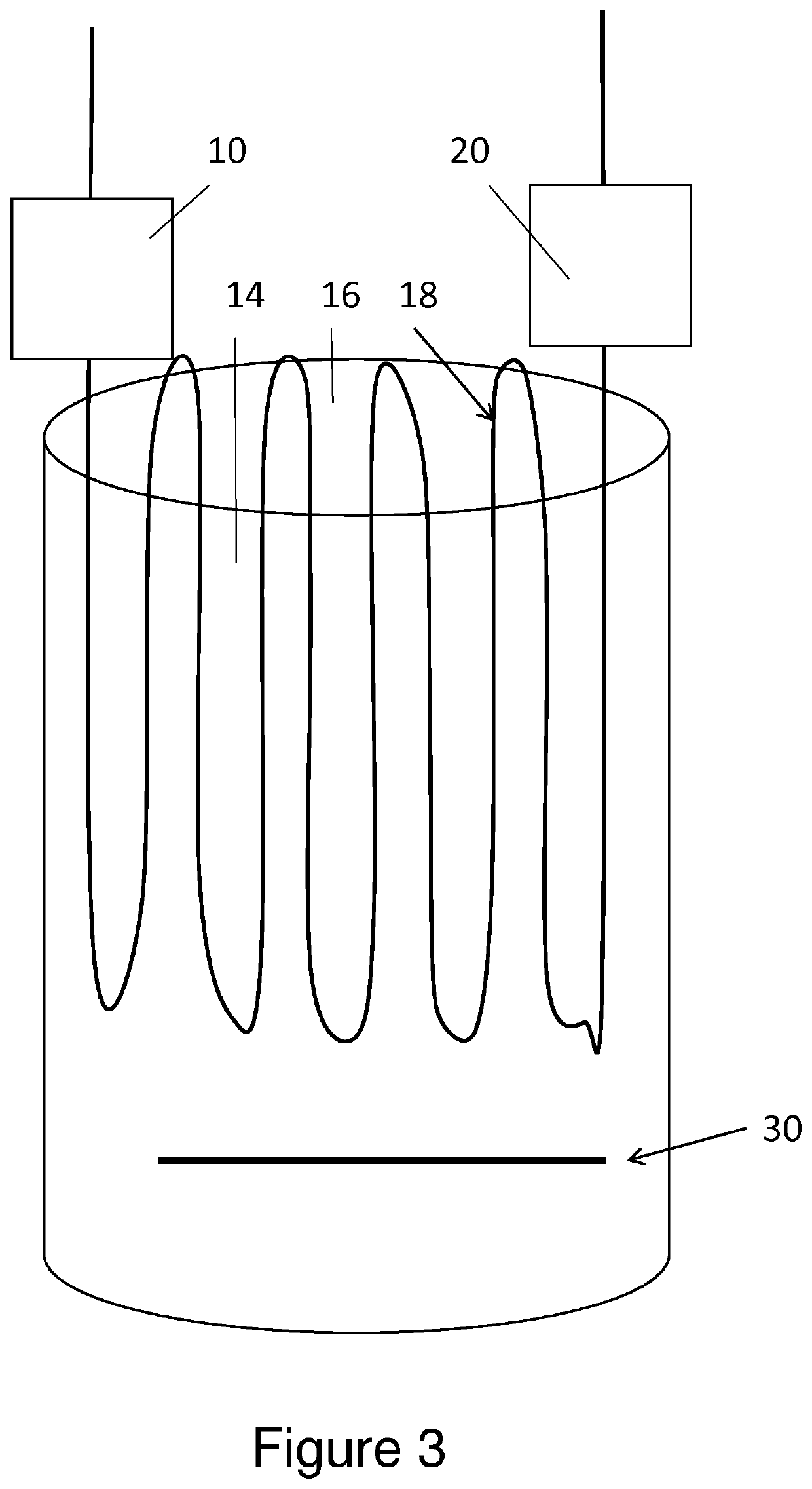
[0040]Also the technique is not very intrusive. In addition, an optical fibre can withstand large temperature variations and different environments, and has a long lifetime. Chances of equipment failure are therefore a lot smaller than e.g. working with an array of temperature sensors. When a large number of discrete sensor elements are used, the output from the sensors may drift with time. Hence measurement of drift or compensation for drift would be advantageous.

Problems solved by technology

The downside is that they have poor thermal conductivity in their solid state, and they are often costly e.g. due to the costs involved in obtaining reliable phase change points.
PCM storage tanks are intrinsically more expensive than the commonly used water buffer systems.
A plurality of optocouplers, with their associated cables, and sealed feedthroughs have to be installed inside the thermal storage vessel increasing the complexity of the design and hence the cost, increasing the possibilities for leaks and increasing the complexity of making many measurements.
The known apparatus does not attempt to measure transmitted light intensity accurately in order to determine the refractive index of a liquid.
In this respect the use of PCMs is associated with several problems.
Because of the low thermal conductivity, the change of phase process such as the melting and freezing process does not occur uniformly throughout the vessel.
Moreover, if there is a change in volume between these states it can result in pressure induced local cavities, further hindering uniformity.
State of charge estimations based on a limited amount of sensors are inaccurate; they cannot take into account this randomness.
Some methods have tried to exploit this volumetric difference by linking the pressure to the ratio of molten / solid PCM but they also are unable to register local cavities.

Method used


Image

  • Optical methods for phase change materials
  • Optical methods for phase change materials
  • Optical methods for phase change materials

Examples


Embodiment Construction

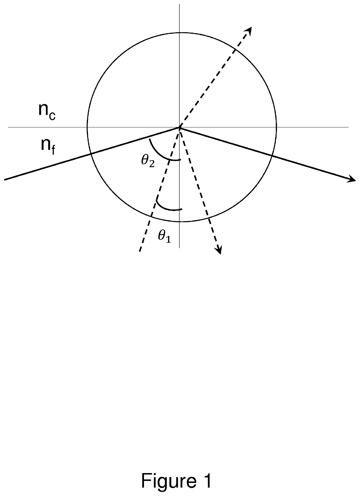
[0051]The present invention will be described with respect to particular embodiments and with reference to certain drawings but the invention is not limited thereto but only by the claims. The drawings described are only schematic and are non-limiting. In the drawings, the size of some of the elements may be exaggerated and not drawn on scale for illustrative purposes. Where the term “comprising” is used in the present description and claims, it does not exclude other elements or steps. Furthermore, the terms first, second, third and the like in the description and in the claims, are used for distinguishing between similar elements and not necessarily for describing a sequential or chronological order. It is to be understood that the terms so used are interchangeable under appropriate circumstances and that the embodiments of the invention described herein are capable of operation in other sequences than described or illustrated herein.

[0052]The aim of the present invention is to ex...


PUM

PropertyMeasurementUnit
refractive indicesaaaaaaaaaa

Abstract

A device for measuring the state of a phase change material inside a vessel, the device includes at least one optical fiber arranged inside the vessel, the optical fiber including a cladding around a core, a light source emitting light coupled into a first end of the at least one optical fiber at a wavelength λ, optical measuring devices for measuring the amount of light at the output at a second end of the at least one optical fiber. The at least one optical fiber also includes a plurality of sections with the cladding removed so that at these sections the core is in direct contact with the phase change material inside the vessel and where the refractive index at the wavelength λ of the core is higher than that of the phase change material in a first phase and lower in a second phase.

Description

FIELD OF THE INVENTION[0001]The present invention pertains to the field of methods and systems for thermal energy storage and of methods and devices for measuring the amount of thermal energy stored in a thermal energy storage that contains phase change materials, as well as a controller for such a thermal energy storage.BACKGROUND OF THE INVENTION[0002]Phase change materials (PCM) are a type of latent heat storage that are capable of storing and releasing large amounts of energy during the process of change of phase. One such phase change is melting and freezing. Other phase changes can be sublimation from solid to gas, or liquid to gas, i.e. boiling. PCMs typically store 5 to 14 times more heat per unit volume than the more commonly used water storage tanks. Hence PCM materials are particularly attractive because they offer high-density energy storage and store heat within a narrow temperature range.[0003]When considered for usage for space heating or the preparation of domestic h...

Claims


Application Information

Patent Timeline
Patent Type & Authority Patents(United States)
IPC IPC(8): G01N21/43G01F23/292F28D20/02G01N21/84
CPCG01F23/2927F28D20/021G01N21/431G01N21/84G01N2021/433G01N2201/0846G01N2201/127G01N2021/8405F28D20/028Y02E60/14G01K11/32
Inventor SALENBIEN, ROBBE
Owner VLAAMSE INSTELLING VOOR TECHNOLOGISCH ONDERZOEK NV VITO
Why Eureka
Try Eureka