Ground terminal for an electronic device

a technology of ground terminal and electronic device, which is applied in the direction of coupling device connection, electrical apparatus, casing/cabinet/drawer details, etc., can solve the problems of reduced ground terminal, reduced safety, and increased risk of ground cable connecting device being connected to the electrical circuit, so as to increase the reliability of personal protection and electrical safety

Active Publication Date: 2019-01-15
AXIS
View PDF12 Cites 1 Cited by
  • Summary
  • Abstract
  • Description
  • Claims
  • Application Information

AI Technical Summary

Benefits of technology

[0008]One object of the present invention is to increase the reliability of personal protection and electrical safety in electric devices.
[0009]According to one aspect, these and other objects are achieved, in full or at least in part by a ground terminal for an electronic device comprises a ground cable connecting device, an electrical switch, and an electrical conductor connecting the ground cable connecting device to the electrical switch. The ground terminal and its ground cable connecting device is configured so that the electrical switch is brought in to a first mode in response to an electrical wire being connected to the ground cable connecting device, the first mode being a mode in which the switch establish electrical conduction between an electrical circuit of the electronic device and the ground cable connecting device. Moreover, the ground terminal and its ground cable connecting device is configured so that the electrical switch is in a second mode when no electrical wire is connected to the ground cable connecting device, the second mode being a mode in which the switch is electrically isolating the electrical circuit of the electronic device and the ground cable connecting device from each other. An advantage of arranging the ground cable connecting device for contact with the electrical circuit of the electrical device when a cable is connected to the ground cable connecting device is that the electrical device becomes less prone to become an electrical hazard for users in the vicinity. The risk of the ground cable connecting device being connected to the electrical circuit of the electrical device when no ground cable is connected to the ground cable connecting device and the ground terminal is decreased. One of the reasons for this is that the chance of a person installing the electrical device forgetting to either electrically isolate the ground terminal from the electric circuit of the electrical device when no ground cable is connected or electrically connect the ground terminal to the electrical circuit of the electrical device when a ground cable is connected is very small due to the specific arrangement.
[0010]According to some embodiments the ground cable connecting device includes a connecting surface, the ground cable connecting device is configured to make the connecting surface exert a clamping force on the electrical wire or a connecting means of the electrical wire. Further, the ground cable connecting device is mechanically connected to the electrical switch. This mechanical connection is configured to bring the electrical switch into the first mode when a movement, in the direction of the clamping force, of the connecting surface and the mechanical connection to the electrical switch is stopped by the electrical wire or the connecting means of the electrical wire pressing against the connecting surface. The advantage of bringing the switch over to the first mode, i.e. bringing the ground cable connecting device in contact with the electrical circuit of the electrical device, in response to the cable, e.g. a ground cable, being clamped by the ground cable connecting device is that the it is easier for the person installing the electrical device to accomplish an electrically safe installation. This results from the connection to the electrical circuit of the electrical device from the ground cable connector being achieved as a result of clamping the cable by the ground cable connecting device, i.e. achieving the connections in one operation. Thereby making it difficult for the person installing the electrical device to only set one of the connections and thereby having an electrical device that is potentially more dangerous than an electrical device where no action has been taken at all.
[0017]According to some embodiments of the electrical device the threads of the first portion of the rod are formed at a distance from the treads of the second portion of the rod in the axial direction of the rod so that the threads of the second portion do not engage with the threads of the opening in the housing until the threads of the first portion of the rod has passed through the opening of the electrical switch and is positioned on the side of the electrical switch not facing the ground cable connection device. The advantage of this arrangement is that the connecting of the ground cable connecting device and thereby the ground terminal to the electrical circuitry of the electrical device may be prohibited even if the ground terminal is removed and then reinserted.

Problems solved by technology

The risk of the ground cable connecting device being connected to the electrical circuit of the electrical device when no ground cable is connected to the ground cable connecting device and the ground terminal is decreased.
One of the reasons for this is that the chance of a person installing the electrical device forgetting to either electrically isolate the ground terminal from the electric circuit of the electrical device when no ground cable is connected or electrically connect the ground terminal to the electrical circuit of the electrical device when a ground cable is connected is very small due to the specific arrangement.
Thereby making it difficult for the person installing the electrical device to only set one of the connections and thereby having an electrical device that is potentially more dangerous than an electrical device where no action has been taken at all.

Method used


Image

  • Ground terminal for an electronic device
  • Ground terminal for an electronic device
  • Ground terminal for an electronic device

Examples


Embodiment Construction

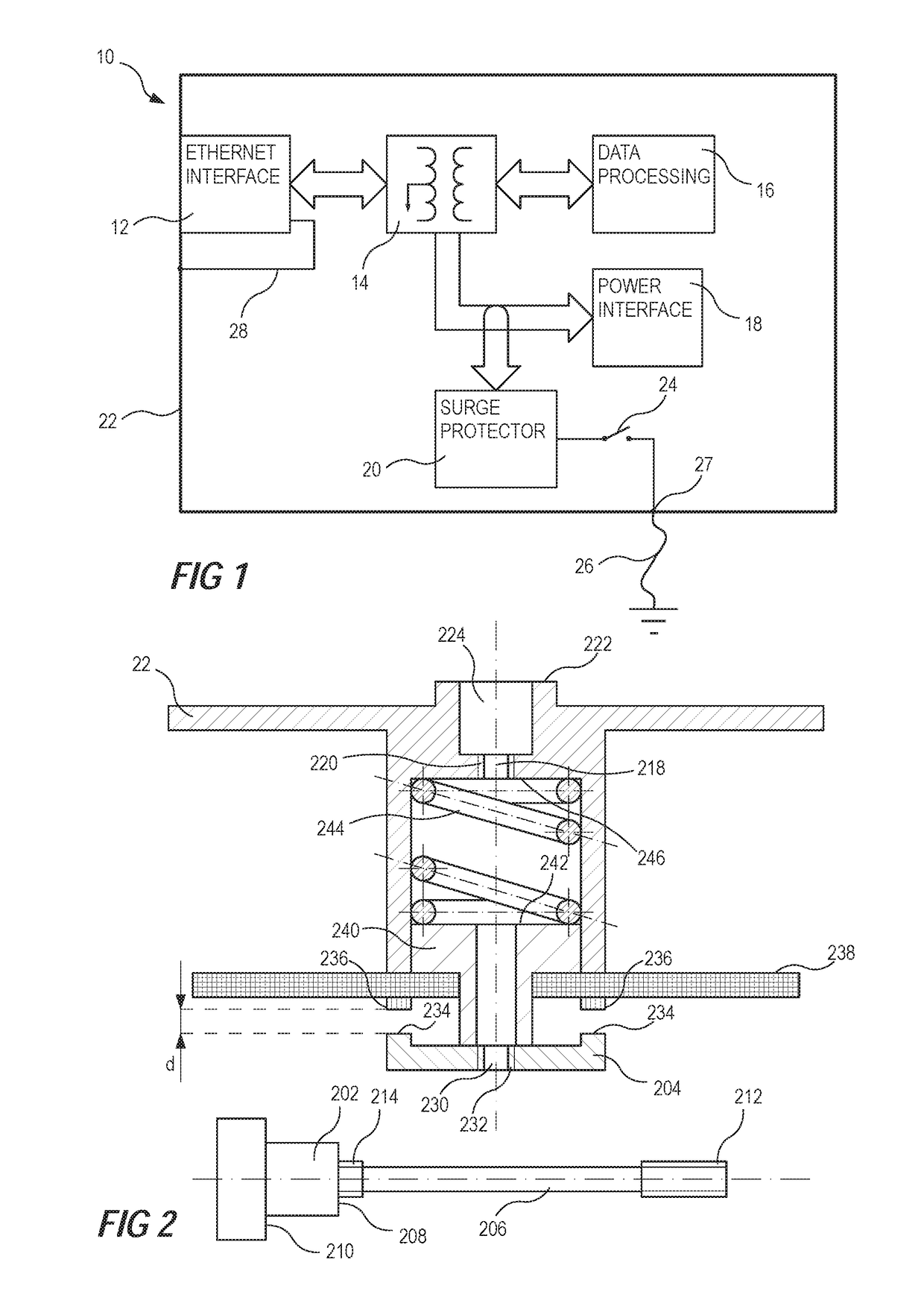
[0031]The present invention relates to personal protection from electrically live parts of electrical devices and especially electrical devices that is powered using Power Over Ethernet, POE. An example of an electrical device in which embodiments of the invention may be implemented is shown in FIG. 1. The electrical device 10 may be any type of electrical device communicating data via an Ethernet interface 12 to a computer network. The electrical device 10 comprises a data and power separation circuit 14, data processing means 16, a power interface 18 providing power to the electrical device 10, a surge protector 20, a housing 22, an electrical switch 24 configured to alternately connect and disconnect the ground of electrical circuitry in the electrical device 10, e.g. a common ground in the electrical device 10, to and from a ground cable 26 or a ground wire 26, The ground cable 26 is connected to the electrical device and the housing of the electrical device at a ground terminal...


PUM


Abstract

The present invention relates to a ground terminal for an electronic device. The ground terminal comprises a ground cable connecting device, an electrical switch, an electrical conductor connecting the ground cable connecting device to the electrical switch. The ground terminal and its ground cable connecting device is configured so that the electrical switch is brought in to a first mode in response to an electrical wire being connected to the ground cable connecting device, the first mode being a mode in which the switch establish electrical conduction between an electrical circuit of the electronic device and the ground cable connecting device. Moreover, the ground terminal and its ground cable connecting device is configured so that the electrical switch is in a second mode when no electrical wire is connected to the ground cable connecting device, the second mode being a mode in which the switch is electrically isolating the electrical circuit of the electronic device and the ground cable connecting device from each other.

Description

RELATED APPLICATION[0001]This application claims the benefit of European Application No. 15202978.1 filed Dec. 29, 2015, which is incorporated by reference herein.TECHNICAL FIELD OF THE INVENTION[0002]The present invention relates to personal safety for persons that may come in contact with electrical devices and in particular it relates to a ground terminal for an electrical device and to an electrical device.BACKGROUND OF THE INVENTION[0003]Electrical products of today are required to provide acceptable protection for users and other people who are handling the electrical device or simply who are at risk for being exposed to electrically conducting parts which accidentally may be live. A common way of protecting people from getting hurt in this situations is to have the electrically conducting part connected to ground. Thereby a circuit breaker, a residual-current Device (RCD), or a Ground Fault Circuit Interrupter (GFCI) will be able to switch off the electric circuit, because of...

Claims


Application Information

Patent Timeline
Patent Type & Authority Patents(United States)
IPC IPC(8): H05K1/00H05K1/02H01R13/703H01R13/648H05K5/02H01R4/40H01R4/34H01R4/64H01R11/28
CPCH05K1/0215H01R4/40H01R13/648H05K5/0247H01R13/7031H01R11/28H01R4/34H01R4/64H01R13/66H01R13/7036
Inventor SVENSSON, SVENBIRCH, MAGNUS
Owner AXIS
Why Eureka
Try Eureka