Taper sleeve for conveyor roller

a conveyor roller and taper technology, applied in the direction of conveyor parts, rollers, transportation and packaging, etc., can solve the problems of adding to the cost and weight of the taper, and achieve the effect of saving material and weight, and minimizing the thickness of the wall

Active Publication Date: 2007-11-27
WYNRIGHT CORP
View PDF12 Cites 37 Cited by
  • Summary
  • Abstract
  • Description
  • Claims
  • Application Information

AI Technical Summary

Benefits of technology

[0003]The sleeve disclosed herein has a tapered wall with radial internal ribs which both strengthen the wall and mate the sleeve to the cylindrical roller core on which it is mounted. The wall thickness is minimized, saving material and weight. The sleeve is pressed onto the roller core. The inner edges of the ribs have an interference fit with the surface of the core.

Problems solved by technology

This adds to the cost and weight of the sleeve.

Method used


Image

  • Taper sleeve for conveyor roller
  • Taper sleeve for conveyor roller

Examples


Embodiment Construction

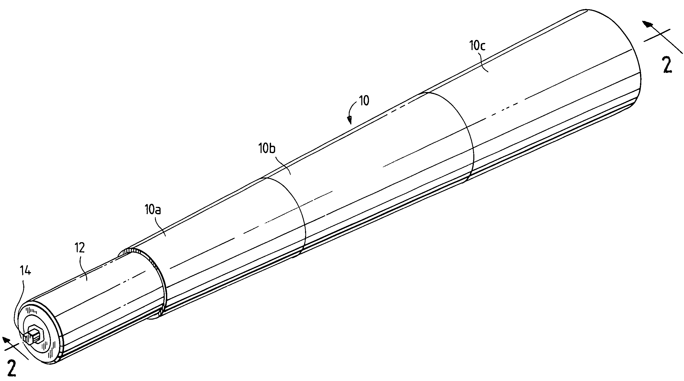
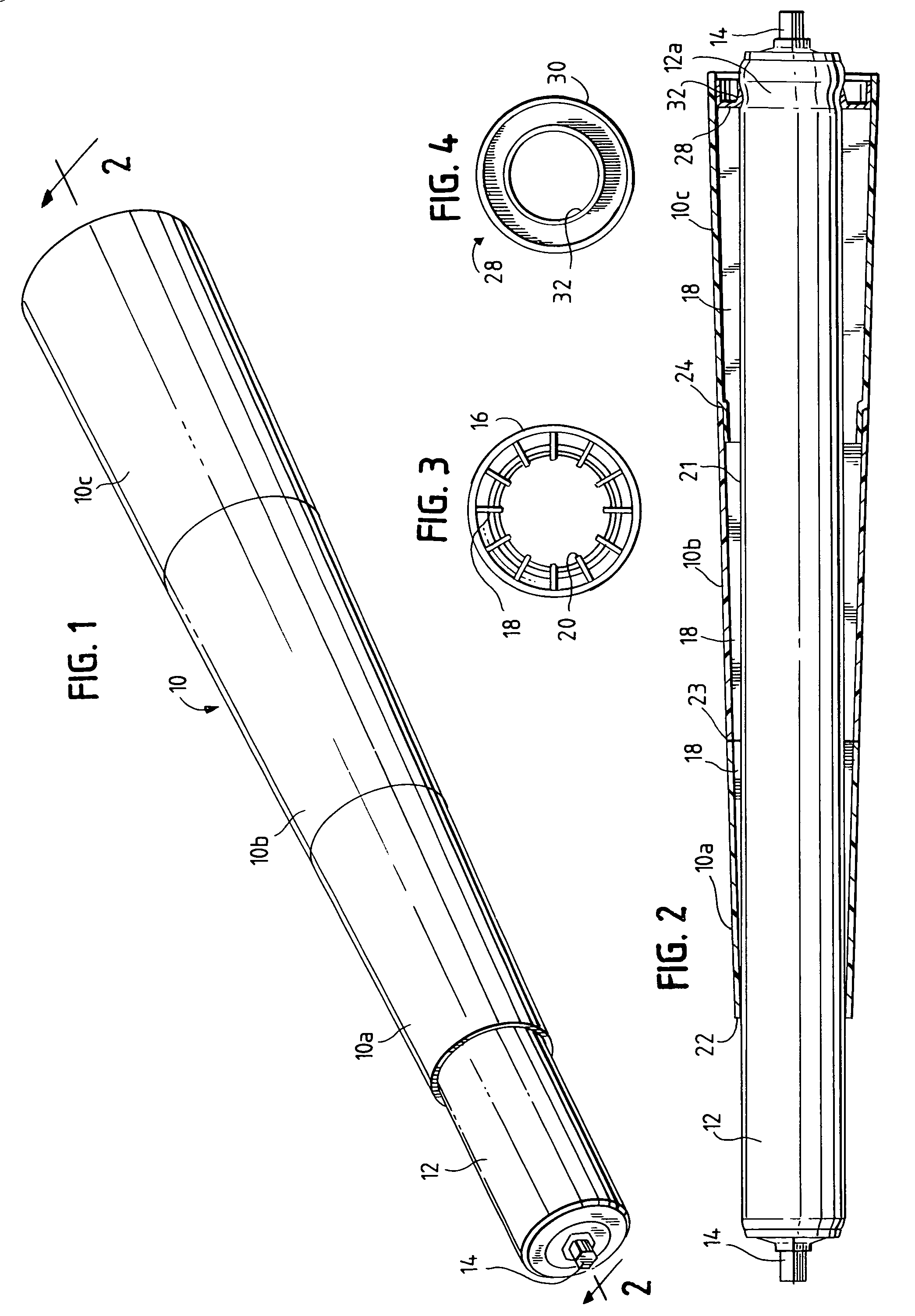
[0008]Plastic tapered sleeve 10 is mounted on a cylindrical core 12 which may be a cylindrical carrying roller for a conveyor. The core has axles 14 for mounting between the conveyor side plates (not shown). Sleeve 10 is preferably composed of segments 10a, 10b, and 10c which join to provide a tapered roller surface.

[0009]Each sleeve segment has a tapered wall 16, FIG. 3, of uniform thickness and having internal radial ribs 18. The inner edges 20 of the ribs rest on the surface of cylindrical core 12 and have interference fit with the surface. Alternatively, or additionally, the inner edges of the ribs may be secured to the core surface with an adhesive, as at 21.

[0010]Typical roller conveyors have a minimum width of 18 inches and are increased in size in 6-inch steps. The smallest segment 10a of the sleeve has a length of 5 inches and successive segments, 10b, 10c have a length of 6 inches. Two segments with a length of 11 inches are used for an 18 inch conveyor. Additional 6-inch ...


PUM


Abstract

A taper sleeve for a conveyor roller used in a curved conveyor section has a taper wall with internal radial ribs which mate with the surface of a cylindrical roller core. The inner edges of the ribs preferably have an interference fit with the core surface.

Description

CROSS-REFERENCE TO RELATED APPLICATIONS[0001]This application is a continuation of Houghton Ser. No. 60 / 698,822 filed Jul. 13, 2005.BACKGROUND OF THE INVENTION[0002]A curved section of a roller conveyor uses tapered rollers to move articles through the curve. It is known to fit a tapered sleeve over a cylindrical core, see Stumpf U.S. Pat. No. 3,934,951. Known sleeves, however, have a relatively thick wall in order to support articles carried by the conveyor without deformation or damage. This adds to the cost and weight of the sleeve.BRIEF SUMMARY OF THE INVENTION[0003]The sleeve disclosed herein has a tapered wall with radial internal ribs which both strengthen the wall and mate the sleeve to the cylindrical roller core on which it is mounted. The wall thickness is minimized, saving material and weight. The sleeve is pressed onto the roller core. The inner edges of the ribs have an interference fit with the surface of the core.BRIEF DESCRIPTION OF THE SEVERAL VIEWS OF THE DRAWING[...

Claims


Application Information

Patent Timeline
Patent Type & Authority Patents(United States)
IPC IPC(8): B65G13/00
CPCB65G39/071B65G39/07
Inventor HOUGHTON, HARRY E.
Owner WYNRIGHT CORP
Why Eureka
Try Eureka