Thermostat with energy saving backlit switch actuators and visual display

a backlit switch actuator and energy saving technology, applied in the direction of lighting and heating apparatus, process and machine control, instruments, etc., can solve the problems of shortening the operating life of devices providing illumination, inefficient heat dissipation, and inefficient control switches, etc., to save power and save energy. , the effect of reducing the life of many illuminating devices

Active Publication Date: 2007-11-27
TRANE INT INC
View PDF10 Cites 183 Cited by
  • Summary
  • Abstract
  • Description
  • Claims
  • Application Information

AI Technical Summary

Benefits of technology

[0005]The present invention also provides a thermostat having an improved arrangement of lighting elements and related structure, such as a visual display and multiple pushbutton type or so-called key switches and the like. Still further, the present invention provides a user operated key or pushbutton type switch for instantly changing the temperature setpoints of the thermostat to the preprogrammed temperature offsets or setback setpoints so as to avoid any lengthy process for implementing the setback temperature settings of the thermostat controller.
[0008]In accordance with yet a further aspect of the present invention an improved configuration and arrangement of user actuated control switches is provided wherein the switch actuators are formed as digitally actuatable members or buttons of a resilient light transmitting material and the switches are provided with an improved arrangement of electrically conductive paths or contact elements formed on the switch actuator members and disposed in relation to a circuit board which supports LED illuminating devices so that the respective actuators are properly illuminated. Still further, the overall arrangement and support for plural switches, a visual display element and associated illuminating devices is provided in an advantageous manner.
[0009]In accordance with still a further aspect of the invention, a thermostat for an air conditioning system is provided with temperature setpoint switch actuators which are continuously illuminated by LED sources and a visual display illuminating device and other switch actuators are energized only for short periods of time by way of an electroluminescent lamp and driver circuit and additional LEDs. Still further, when any one of the switch actuators is actuated, the electroluminescent lamp and all LED sources for switch actuators are energized for a predetermined period of time whereby the thermostat may be operated in a dark environment. The continuously illuminated temperature setpoint switch actuators provide a way of locating the thermostat in a dark environment without reducing the life of many of the illuminating devices and without requiring an ambient light level sensor. In this way, the arrangement for illuminating the thermostat display and control switches conserves power and is suitable for use in applications where only low levels of power are available at the thermostat, such as in so-called power stealing applications wherein there is no common connection between the thermostat and a control circuit transformer.
[0010]In accordance with yet a further aspect of the present invention, a thermostat is provided which includes an illuminated, so-called energy savings switch which may be actuated by the thermostat user at any time to change the temperature setpoints of the thermostat to the so-called offset or setback temperature setpoints by a single actuation of the energy saving switch. A second actuation of the energy saving switch returns the temperature setpoints of the thermostat to the previous settings. In this way, a user of the thermostat may conveniently change the temperature setpoints from the so-called normal operating condition values to the setback temperature values quickly and conveniently and without requiring the user to go through a lengthy process for changing a time based activation of the setback temperature values.

Problems solved by technology

However, thermostats with continuously lit visual displays and control switches are inefficient since they continuously consume energy when not required to do so, and the operating lives of the devices providing illumination, such as electroluminescent lamps and light emitting diodes are shortened.

Method used


Image

  • Thermostat with energy saving backlit switch actuators and visual display
  • Thermostat with energy saving backlit switch actuators and visual display
  • Thermostat with energy saving backlit switch actuators and visual display

Examples


Embodiment Construction

[0023]In the description which follows, like elements are marked throughout the specification and drawings with the same reference numerals, respectively. The drawing figures are not necessarily to scale and certain features and elements may be shown in somewhat schematic or generalized form in the interest of clarity and conciseness.

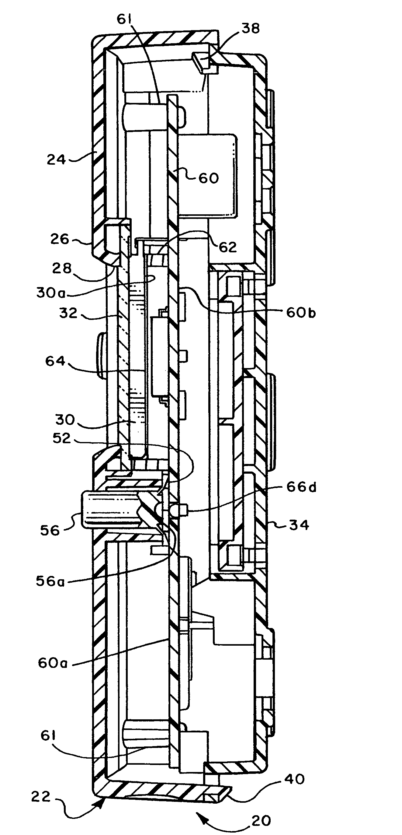
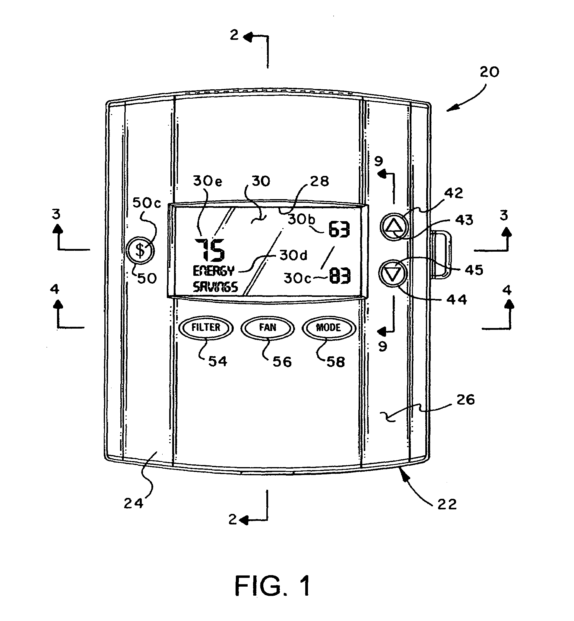
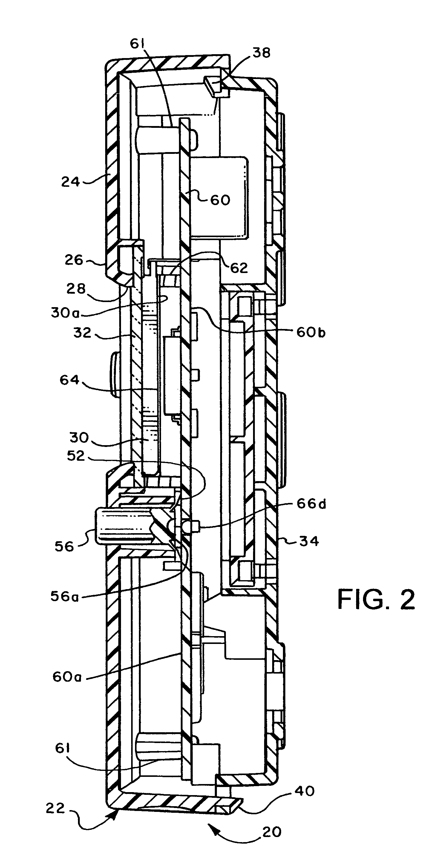
[0024]Referring briefly to FIG. 1, a thermostat, typically used for a residential or commercial air conditioning system, is illustrated and generally designated by the numeral 20. The thermostat 20 is provided with a generally rectangular two part housing 22 which includes a somewhat shell-like cover member 24, see FIG. 6 also, characterized by a front wall 26 having a generally rectangular opening 28 formed therein. Opening 28 provides for a user of the thermostat 20 to view a visual display 30, of a type to be described further herein. As shown in FIGS. 2 and 6, a suitable transparent lens 32 is adapted to be fitted in the opening 28 for covering the ...


PUM


Abstract

An air conditioning system thermostat includes a visual display and plural switch actuators, respectively backlit by an electroluminescent lamp and LED light sources mounted on a circuit board disposed in a thermostat housing. A control circuit causes at least one switch actuator to be illuminated continuously and the light sources for the display and the remaining switch actuators are illuminated in response to actuation of any one of the switch actuators. Switch contact elements mounted on the switch actuators and the circuit board provide advantageous positioning of the LED light sources for the switch actuators. An energy savings switch actuator allows the control circuit to directly assume setback temperature settings in response to a first actuation and a second actuation resets the thermostat to the initial user set temperature settings.

Description

BACKGROUND OF THE INVENTION[0001]User operated controllers for air conditioning systems, commonly known as thermostats, should provide lighting for the visual display of control features, including actual temperature, temperature setpoints and operating mode, as well as lighting for the keypad switches which are user operated to set the control functions of the thermostat and to observe system operating conditions. However, thermostats with continuously lit visual displays and control switches are inefficient since they continuously consume energy when not required to do so, and the operating lives of the devices providing illumination, such as electroluminescent lamps and light emitting diodes are shortened. Accordingly, there has been a need to improve the lighting features of air-conditioning system thermostats whereby a thermostat visual display is lighted only when needed and certain user actuated switches or so-called key or pushbutton switches are illuminated also only when n...

Claims


Application Information

Patent Timeline
Patent Type & Authority Patents(United States)
IPC IPC(8): G05D24/00
CPCG05D23/1905
Inventor GARRETT, CARL L.ERWIN, W. RANDALLSTORM, TIMOTHY W.
Owner TRANE INT INC
Why Eureka
Try Eureka