Determining the lighting conditions surrounding a device

Active Publication Date: 2007-11-27
NOKIA TECHNOLOGLES OY
View PDF14 Cites 14 Cited by
  • Summary
  • Abstract
  • Description
  • Claims
  • Application Information

AI Technical Summary

Benefits of technology

[0014]It is an advantage of the invention that the measured light intensity of the color filtered light provides a detailed information on the current lighting conditions. Such an information can be employed in particular for adapting settings of the device which relate to a function that depends on the surrounding lighting conditions.
[0015]Since the color filtering function of the display is used for performing luminance measurements, no additional hardware is required for the color filtering of the measured light.
[0016]Preferred embodiments of the invention become apparent from the subclaims.
[0017]The measured light intensity of the color filtered light can be employed in particular as a basis for fine-tuning the settings of the display when presenting information to the user of the device. The invention thus enables an adaptation of color presentations to differing lighting conditions, and thereby an improved quality of presentations on the display. It allows in particular to obtain an optimum balance of colors and contrasts in a given environment at a given time.

Problems solved by technology

Usually, there is not much information available on the characteristics of LCD displays released by different manufacturers.
Some displays may turn out to perform well under specific light conditions, but poorly under other light conditions.
But even the presentation on displays of a high quality might be difficult to perceive in extrem

Method used


Image

  • Determining the lighting conditions surrounding a device
  • Determining the lighting conditions surrounding a device

Examples


Example

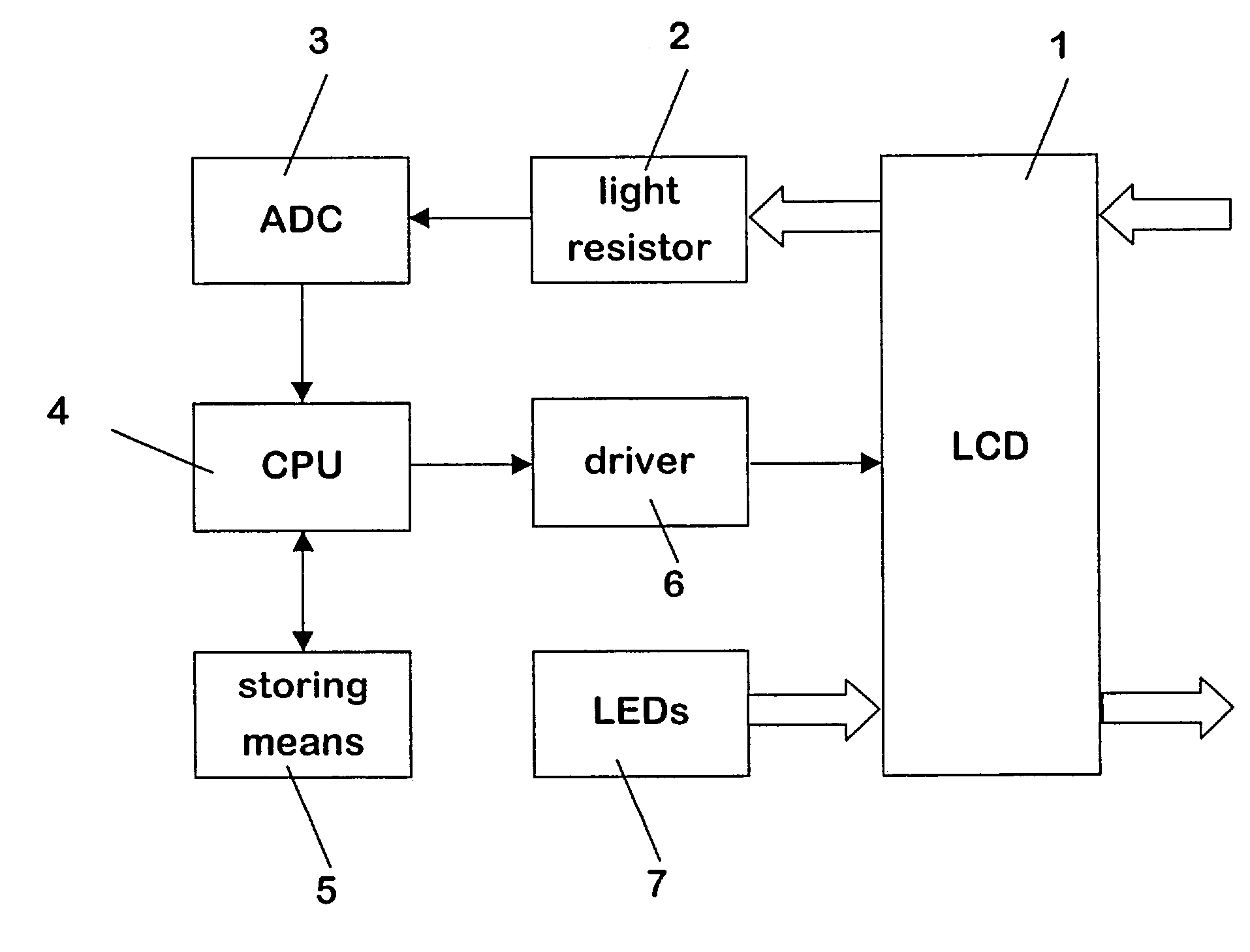
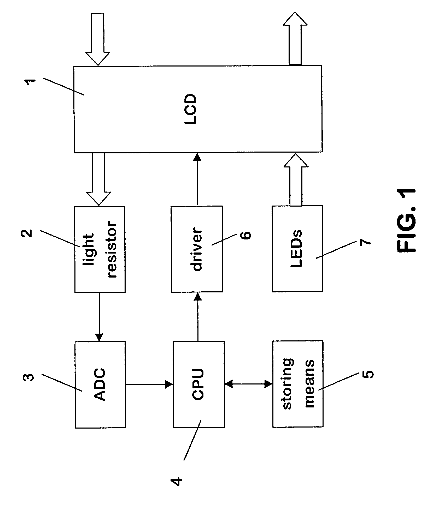
[0041]FIG. 1 shows components of a mobile terminal with a transmissive LCD color display 1, which can be fine-tuned according to the invention.

[0042]The transmissive LCD color display 1 is a known LCD color display, in which each pixel can be turned to white, red, green or blue. Equally, a combination of the three main colors RGB can be selected for each pixel. In addition, the brightness of each pixel can be varied for each color. The LCD display 1 has mainly good reflective characteristics.

[0043]The mobile terminal further comprises a light resistor 2 which is positioned immediately behind one of the corners of the LCD display 1. The light resistor 2 is able to measure the light intensity of light passing at the location at which the light resistor 2 is positioned through the LCD display 1 from the outside. The light resistor 2 is connected via an ADC 3 to a central processing unit (CPU) 4 of the mobile terminal.

[0044]The CPU 4 has access to storing means comprising a data table 5...


PUM


Abstract

The invention relates to a method for determining the lighting conditions surrounding a device comprising a transmissive color LCD display 1. In order to obtain a detailed information on the lighting conditions, it is proposed that the method comprises measuring within the device the intensity of light passing through the LCD display 1 from outside of the device, while no backlight is switched on. The light is color filtered by at least part of the LCD display 1 with a known color distribution. The invention equally relates to a device comprising means for carrying out the proposed method.

Description

CROSS REFERENCE TO RELATED APPLICATIONS[0001]The present application claims priority under 35 USC §119 to European Patent Application No. EP 02 011 308.0 filed on May 23, 2002.FIELD OF THE INVENTION[0002]The invention relates to a method for determining the lighting conditions surrounding a device comprising a transmissive color LCD (liquid crystal display). The invention relates equally to a device comprising a transmissive LCD color display.BACKGROUND OF THE INVENTION[0003]It is well known in the state of the art to supply a device, e.g. a mobile terminal, with a color LCD display, which allows presentation of information in color to a user of the terminal.[0004]A color LCD display comprises different pixels, each of which can be set to be white, red, green and / or blue. The distribution of the colors to the different pixels of the display is selected according to the information that is currently to be presented. In addition, the brightness of each color can be set for each presen...

Claims


Application Information

Patent Timeline
IPC IPC(8): G09G3/36G09G5/00
CPCG09G3/3611G09G2320/066G09G2320/0693G09G2320/0673G09G2320/0666
Inventor RUNOLINNA, MIKA
Owner NOKIA TECHNOLOGLES OY
Why Eureka
Try Eureka