Compressor module for compressing gas and compressor equipped therewith

Active Publication Date: 2020-07-07
ATLAS COPCO AIRPOWER NV
24 Cites 0 Cited by

AI-Extracted Technical Summary

Problems solved by technology

These pipes and connections are not only expensive, but are also subject to defects and leaks that can lead to higher maintenance costs of such compressor modules.
A disadvantage of air cooling is that the ventilation air that removes the heat of compression is difficult to apply usefully.
It is also difficult to cool to a low temperature with air cooling because to realise a small temperature difference, also called delta T, between the ventilation air temperature and the medium to be cooled, very large coolers are required that are very expensive.
For example, in practice with direct or indirect air cooling, for example by means of an oil circuit with radiator, a compresso...

Method used

[0074]Because both the coolant and the oil absorb heat from the motor 5 and in the compressor element 2, t...

Benefits of technology

[0049]With one or more such compressor modules a compressor can be easily made, whereby these one or more compressor modules are affixed in a closed casing without forced ventilation with gas from outsid...

Abstract

A compressor module for compressing gas composed of a compressor element with a housing with integrated compressor element cooler; a motor and a gas cooler for cooling the compressed gas originating from the compressor element. The gas cooler includes a primary section through which the gas to be cooled can be guided and a secondary section that is in heat-exchanging contact with the primary section. A first cooling circuit can guide a coolant through the secondary section of the gas cooler or through a section thereof and a second cooling circuit can guide a coolant through the compressor element cooler. The first cooling circuit and the second cooling circuit are joined together in series or in parallel and are guided to a common output.

Application Domain

Technology Topic

Image

  • Compressor module for compressing gas and compressor equipped therewith
  • Compressor module for compressing gas and compressor equipped therewith
  • Compressor module for compressing gas and compressor equipped therewith

Examples

  • Experimental program(1)

Example

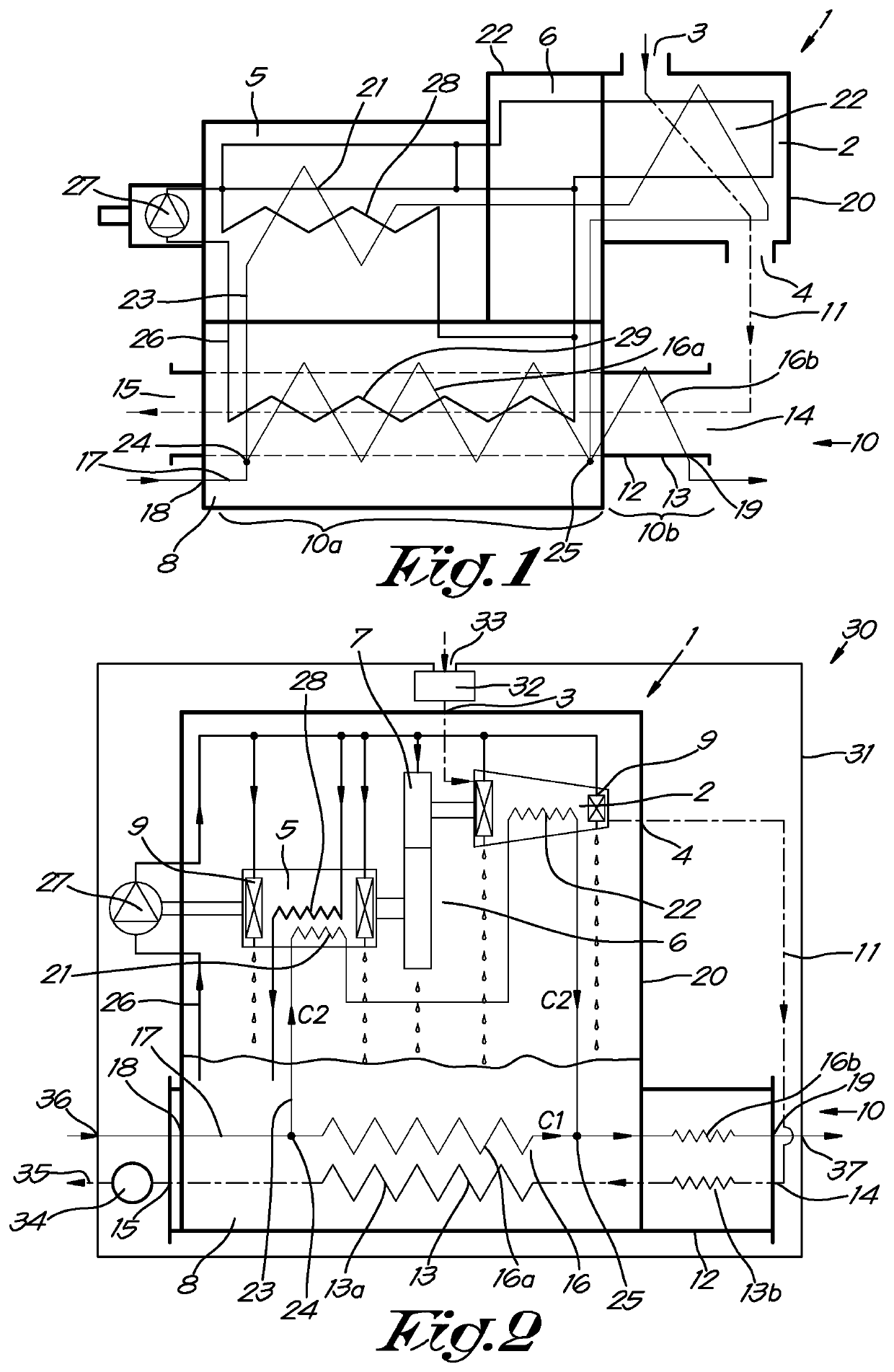
[0061]The compressor module 1 shown in FIGS. 1 and 2 is composed of a compressor element 2 with an input 3 for gas to be compressed and an output 4 for the compressed gas; an electric motor 5; in this case a gearbox 6 between the compressor element 2 and the motor 5 with gears 7 for the transmission of the motor torque to the compressor element 2; an oil sump 8 with oil for lubricating and cooling the bearings 9 of the motor 5 and the compressor element 2 and of the gears 7; and a gas cooler 10 for cooling the compressed gas originating from the compressor element 2, whereby this gas cooler 10 is connected via a pipe 11, shown schematically, to the output 4 of the compressor element 2.
[0062]In this case the gas cooler 10 comprises a tube 12 that forms the primary section 13 of the gas cooler 10 through which the compressed gas originating from the compressor element 2 can be guided via a gas inlet 14 to a gas outlet 15, to which a network of users of compressed gas can be connected, whereby this tube 12 is in heat-exchanging contact with the secondary section 16 of the gas cooler 10 that extends as a first cooling circuit 17 in or around the tube 12, and which is provided with an input 18 and an output 19 for a coolant that is carried through it in the direction of the arrow C1.
[0063]Primary here means the part of the heat exchanger that the medium to be cooled flows through, in this case compressed gas, and secondary means the part of the heat exchanger that the coolant flows through.
[0064]The gas cooler 10 extends, by a sump section 10a, transversely through the oil sump 8 in heat-exchanging contact with the oil in the oil sump 8 and an outer section 10b outside the oil sump 8.
[0065]The primary section 13 of the gas cooler 10 is thus split into a sump section 13a in the sump section 10a of the gas cooler 10 and an outer section 13b in the outer section 10b of the gas cooler 10.
[0066]In the same way the secondary section 16 of the gas cooler 10 is split into a sump section 16a and an outer section 16b.
[0067]In the example discussed here, the first cooling circuit 17 is composed of the sump section 16a and the outer section 16b of the secondary section 16 of the gas cooler 10.
[0068]The housing 20 of the compressor module is composed of the housings of the compressor element 2; the motor 5; the gearbox 6; the gas cooler 10 and the oil sump 8.
[0069]A motor cooler 21 and a compressor element cooler 22 are integrated in the housing 20 of the compressor module, whereby this motor cooler 21 and compressor element cooler 22 are each formed by internal channels of the housing that wind around the rotor of the motor 5 and around the rotors of the compressor element 2 respectively for example, and through which a coolant can be driven.
[0070]In addition to the first cooling circuit 17, the compressor module 1 comprises a second cooling circuit 23 for a coolant that is driven in series first through the aforementioned motor cooler 21 and then through the compressor element cooler 22 in the direction of the arrows C2.
[0071]In the example of FIGS. 1 and 2, the second cooling circuit 23 is connected in parallel to a section of the first cooling circuit 17, more specifically to the section of the first cooling circuit that is formed by the sump section 16a of the secondary section 16 of the gas cooler 10 that is in heat-exchanging contact with the oil in the oil sump 8 and which in this way is bypassed by the second cooling circuit 23.
[0072]The second cooling circuit 23 is thereby tapped off from the first cooling circuit 17 at a point 24 at the input 18 of the first cooling circuit 17 and thereafter connects back to the first cooling circuit 17 at an intermediary point 25 of the secondary section 16 of the gas cooler 10 that is located between the input 18 and the output 19 of this secondary section 16, preferably at an intermediary point 25 in the vicinity of the transition between the sump section 10a and the outer section 10b of the cooler 10.
[0073]The compressor module 1 is further provided with a closed oil circuit 26 with an oil pump 27, which in this case is affixed on the motor 5 and is driven by it and which pumps oil around from the oil sump 8 through internal channels in the housing 20 of the compressor module 1 to the aforementioned bearings 9 of the motor 5 and of the compressor element 2, and to the gearbox 6 from which the oil flows back to the oil sump 8. The internal channels of the oil circuit 26 are thereby guided through the housing of the motor 5 and the housing of the compressor element 2 in heat-exchanging contact with the coolant of the second cooling circuit 23 that is guided through the motor cooler 21 and through the compressor element cooler 22, such that the oil circuit in the motor 5 and in the compressor element 2 acts as an oil cooler 28 that absorbs heat from the motor 5 and from the compressor element 2 during the operation of the compressor module and emits this heat to the coolant of the second cooling circuit 23 that itself also absorbs heat from the motor 5 and from the compressor element 2, and as a result its temperature increases greatly.
[0074]Because both the coolant and the oil absorb heat from the motor 5 and in the compressor element 2, the motor 5 and the compressor element 2 itself are kept relatively cool, which leads to better efficiency.
[0075]The second cooling circuit 23 and the oil circuit 26 are formed by internal channels, without there being external pipes.
[0076]The oil pump 27 can be affixed both internally and externally, but preferably without external pipes connected to the oil circuit 26.
[0077]An oil filter can also be provided that is preferably mounted on the housing 20 of the compressor module 1 without pipes. Preferably the oil filter is incorporated in the oil circuit 26 after the oil pump 27 and before the oil is distributed for the lubrication of bearings and/or gears.
[0078]The oil that is driven via the oil circuit 23 to the bearings 9 and to the gearbox 6 not only ensures adequate lubrication but also ensures cooling of the bearings 9 and the gears 7. The oil thereby absorbs heat from the bearings 9 and from the gearbox 6 and then flows back to the oil sump 8 where the oil is collected and cooled by the contact with the sump section 16a of the first cooling circuit 17, which as a result also plays a role as an oil cooler 29 for the oil in the oil sump 8, in addition to its role in the gas cooler 10.
[0079]In this way, the coolant that is guided through the first cooling circuit 17 not only absorbs heat from the compressed gas to be cooled originating from the compressor element 2, but also absorbs heat from the oil in the oil sump 8 after it has circulated in the compressor module 1 and has absorbed heat there. In this way the temperature of the coolant in the sump section 10a of the cooler 10 also rises considerably and then mixes with the coolant originating from the second cooling circuit 23 at the intermediary point 25, after which the coolant undergoes an extra temperature increase due to the heat-exchanging contact with the uncooled hot compressed gas originating directly from the compressor element 2.
[0080]In this way, a compressor module 1 according to the invention enables a coolant to be obtained at the output 19 of the first cooling circuit 17 with a high temperature that can be used for all kinds of useful applications such as heating or similar, or as hot water if water is used as a coolant for energy recovery.
[0081]It is clear from the foregoing that the gas cooler 10, the first and second cooling circuit 17, 23, as well as the oil circuit 26, with the possible exception of the oil pump 27 and the oil filter, are fully integrated in the housing 20 of the compressor module 1 via internal channels, and this without using any external pipes.
[0082]FIG. 2 shows a compressor 30 with one single compressor module 1 according to the invention that is built into a casing 31 without ventilation by outside air, and which is provided with an inlet filter 32 with an inlet 33 in the casing to the input 3 of the compressor element 2, with a pipe 11 that connects the output 4 of the compressor element 2 to the gas inlet 14 of the gas cooler 10 and whereby a pressure vessel 34 is possibly connected to an outlet 35, at the gas output 15 of the gas cooler 10, to which a network of consumers of compressed and cooled gas can be connected.
[0083]The casing 31 is thus completely closed and soundproof, save for a few passages for the inlet 33 for the gas to be compressed and an outlet 35 for the compressed gas and for the supply 36 and outlet 37 of the coolant, as well as for electric cables, not shown in the drawings, for the power supply of the motor 5, the motor 5 drive and similar.
[0084]The gas that flows through the casing 31 is thus only the gas that is compressed by the compressor 30.
[0085]The use of a compressor module 1 according to the invention adequately follows from the above description.
[0086]When the compressor element 2 is driven by the motor 5 gas is drawn in and compressed, whereby the temperature of the gas can increase sharply due to compression. The compressed gas is guided through the primary section 13 of the gas cooler 10 where it is cooled by the heat-exchanging contact with the coolant that flows through the first cooling circuit 17 in the secondary section 16 of the gas cooler 10.
[0087]The second cooling circuit 23 guides the coolant through the motor cooler 21 of the motor 5 and through the compressor element cooler 22 of the compressor element 2, where this cooling circuit 23 ensures the cooling of the motor 5 and of the compressor element 2 that will remain relatively cool as a result.
[0088]The heat that the coolant thereby absorbs from the motor 5 and from the compressor element 2 ensures supplementary heating of the coolant in the sump section 16a of the secondary section 16 of the gas cooler 10, such that the temperature of this coolant increases substantially at the combined output 19 of the first and second cooling circuit 17, 23 to a value that enables the absorbed heat of the coolant to be usefully employed.
[0089]Simultaneously, the oil pump 27 is driven that drives oil from the oil sump 8 through the bearings 9 and across the gears 7, where this oil absorbs the heat generated in the bearings 9 and gears 7 that are thereby kept cool by the oil that was first cooled by the heat-exchanging contact of the oil with the coolant in the oil sump 8 and in the motor 5 and the compressor element 2.
[0090]In this way the compressor module 1 is kept cool without any form of ventilation, while simultaneously a maximum of heat is absorbed by the coolant, heat can that can be usefully employed for heating or similar.
[0091]Analogous to FIG. 1, FIG. 3 schematically shows a composition of two compressor modules 1 according to the invention, respectively a low pressure compressor module 1′ and a high pressure compressor module 1″ that connects in series via a pressure pipe 38 at its input 3 to the gas outlet 15 of the low pressure compressor module 1′.
[0092]FIG. 4 shows these two compressor modules 1′ and 1″ built into a casing 31 of a two stage compressor 30.
[0093]The casing is provided with two passages, respectively for the inlet 33 of the gas to be compressed that is drawn in by the low pressure compressor module 1′ and for the outlet of the compressed gas originating from the high pressure compressor module 1″.
[0094]For the cooling a supply 36 for coolant is provided in the casing that is divided over the two compressor modules 1′ and 1″ and two outlets, respectively an outlet 37 for the coolant originating from the low pressure compressor module 1′ and an outlet 37 for the coolant originating from the high pressure compressor module 1″. Both outlets 37 can also converge before leaving the casing 31.
[0095]In this case the two compressor modules 1′ and 1″ are provided with a control valve 39 at the location of the connection of the second cooling circuit 23 to the first cooling circuit 17 and of a connection 40 for connecting to a cooling circuit of another compressor module.
[0096]The control valve 39 of the low pressure compressor module 1′ is open, while it is closed in the high pressure compressor module 1″ and the two connections 40 are connected together by means of a pipe 41.
[0097]In this way the coolant of the second cooling circuit 23 of the high pressure compressor module 1″ meets the coolant of the second cooling circuit 23 of the low pressure compressor module 1′ that converge with the coolant of the first cooling circuit 17 of the low pressure compressor module 1′ at the intermediary point 25 of the low pressure compressor module 1′, such that the temperature of the coolant at the outlet 37 of the low pressure compressor module 1′ increases further with respect to the arrangement of FIGS. 1 and 2.
[0098]The gas cooler 10 of the low pressure compressor module 1′ is used in this configuration as an intercooler for the compressed gas from the low pressure compressor module 1′ before it is compressed by the high pressure compressor module 1″.
[0099]The gas cooler 10 of the high pressure compressor module 1″ is then used as an aftercooler for the compressed gas of the high pressure compressor module 1″ before it is supplied to the network, and is only cooled by a part of the coolant that is not guided to the low pressure compressor module 1′ via the second cooling circuit 23 of the high pressure compressor module 1″, whereby this part of the coolant that flows through the gas cooler 10 is also removed via the outlet 37.
[0100]With such a compressor 30 a gas can be compressed very efficiently without ventilation and with two flow rates of a coolant that can be usefully used to be able to recover energy from the heat that is generated by compression, in the bearings and gears and similar.
[0101]FIG. 5 shows a variant of a compressor 30 whereby an extra aftercooler 10c, that can be both external and internal, is provided downstream from the gas cooler 10 of the compressor module 1 and in series with it.
[0102]FIG. 6 shows another variant of a compressor 30 according to the invention, whereby in this case the gas cooler 10 extends through the oil sump 8 over its entire length, so that the gas cooler 10 then only contains a sump section 10a without outer section 10b. This missing outer section and can replaced if necessary by an extra external cooler (not shown).
[0103]In the example of FIGS. 1 to 6, the entire sump section 10a of the gas cooler 10 is bypassed each time by the second cooling circuit 23, although it is possible according to a variant that only a section of the sump section 10a is bypassed.
[0104]FIG. 7 shows a variant whereby in this case the first cooling circuit 17 and the second cooling circuit 23 are connected together in series with an input 18 and an output 19 to successively guide the coolant through both cooling circuits, for example first through the first cooling circuit 17 and then through the second cooling circuit 23 or in the reverse order.
[0105]FIG. 8 shows another possible variant of a compressor 30 according to the invention, whereby in this case the gas cooler 10 is constructed completely externally without a sump section 10a.
[0106]Although there is a gearbox 6 in all variants described above, it is not excluded that the motor 5 drives the compressor element 2 directly, without a gearbox, for example in the case of an electric motor with a variable speed.
[0107]The present invention is by no means limited to the embodiments described as an example and shown in the drawings, but a compressor module according to the invention and a compressor equipped therewith can be realised in all kinds of forms and dimensions without departing from the scope of the invention.

PUM

no PUM

Description & Claims & Application Information

We can also present the details of the Description, Claims and Application information to help users get a comprehensive understanding of the technical details of the patent, such as background art, summary of invention, brief description of drawings, description of embodiments, and other original content. On the other hand, users can also determine the specific scope of protection of the technology through the list of claims; as well as understand the changes in the life cycle of the technology with the presentation of the patent timeline. Login to view more.

Similar technology patents

Scouring pad

Owner:3M INNOVATIVE PROPERTIES CO

Data receiving device

ActiveUS7277501B2Reduce timeEasily makeFrequency/rate-modulated pulse demodulationAmplitude-modulated carrier systemsFrequency bandQuadrature signal
Owner:PANASONIC CORP

Classification and recommendation of technical efficacy words

  • Additional requirement
  • Easily make

Environmental air control system

InactiveUS7770405B1Additional requirementSpace heating and ventilation safety systemsSpace heating and ventilation control systemsRefrigerantEvaporator
Owner:DC & BV FRANCE HLDG

Method and device for impulse response measurement

InactiveUS20060203894A1Reduce impulse responseAdditional requirementPolarisation/directional diversityError prevention/detection by diversity receptionSignal-to-interference ratioEngineering
Owner:NOKIA CORP

System and method to trim reference levels in a resistive memory

ActiveUS20150092469A1Additional requirementDigital storageReference levelReference cell
Owner:QUALCOMM INC

Closed-loop control for a gas turbine with actively stabilized compressor

InactiveUS20100196137A1Additional requirementOperational reliability be increasePump componentsWind motor controlAirplaneGas turbines
Owner:MTU AERO ENGINES GMBH

Data-handling, business systems and games

InactiveUS20060030402A1Competitiveness be decreaseEasily makeVideo gamesCommerceMonetary AmountBank account
Owner:CHANDRAKUMAR APPUTHURAI +1

Collapsible metal air battery

InactiveUS20070154766A1Easily makeEffectively dischargeFuel and primary cellsDeferred-action cellsMagnesiumEngineering
Owner:BAIK DONG SOO +1
Why Eureka
Try Eureka