Method for producing an RFID transponder product, and RFID transponder product produced using the method

Active Publication Date: 2013-04-02
LINXENS HLDG SAS
View PDF11 Cites 1 Cited by
  • Summary
  • Abstract
  • Description
  • Claims
  • Application Information

AI Technical Summary

Benefits of technology

[0034]In one embodiment of the method it may be provided that the naked chip contacts the chip terminals of the antenna structure and the connecting structure via an adhesive. This embodiment has advantages compared to soldering methods, which are still possible

Problems solved by technology

RFID transponder products can be subject to strong mechanical stress, which leads to particularly high requirements for the integration of the chip into the product as well as the electric connection to the transponder antenna.
The processing of naked chips,

Method used


Image

  • Method for producing an RFID transponder product, and RFID transponder product produced using the method
  • Method for producing an RFID transponder product, and RFID transponder product produced using the method
  • Method for producing an RFID transponder product, and RFID transponder product produced using the method

Examples


Example

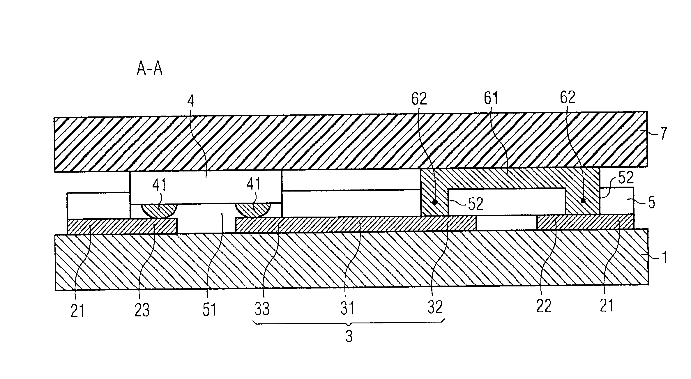
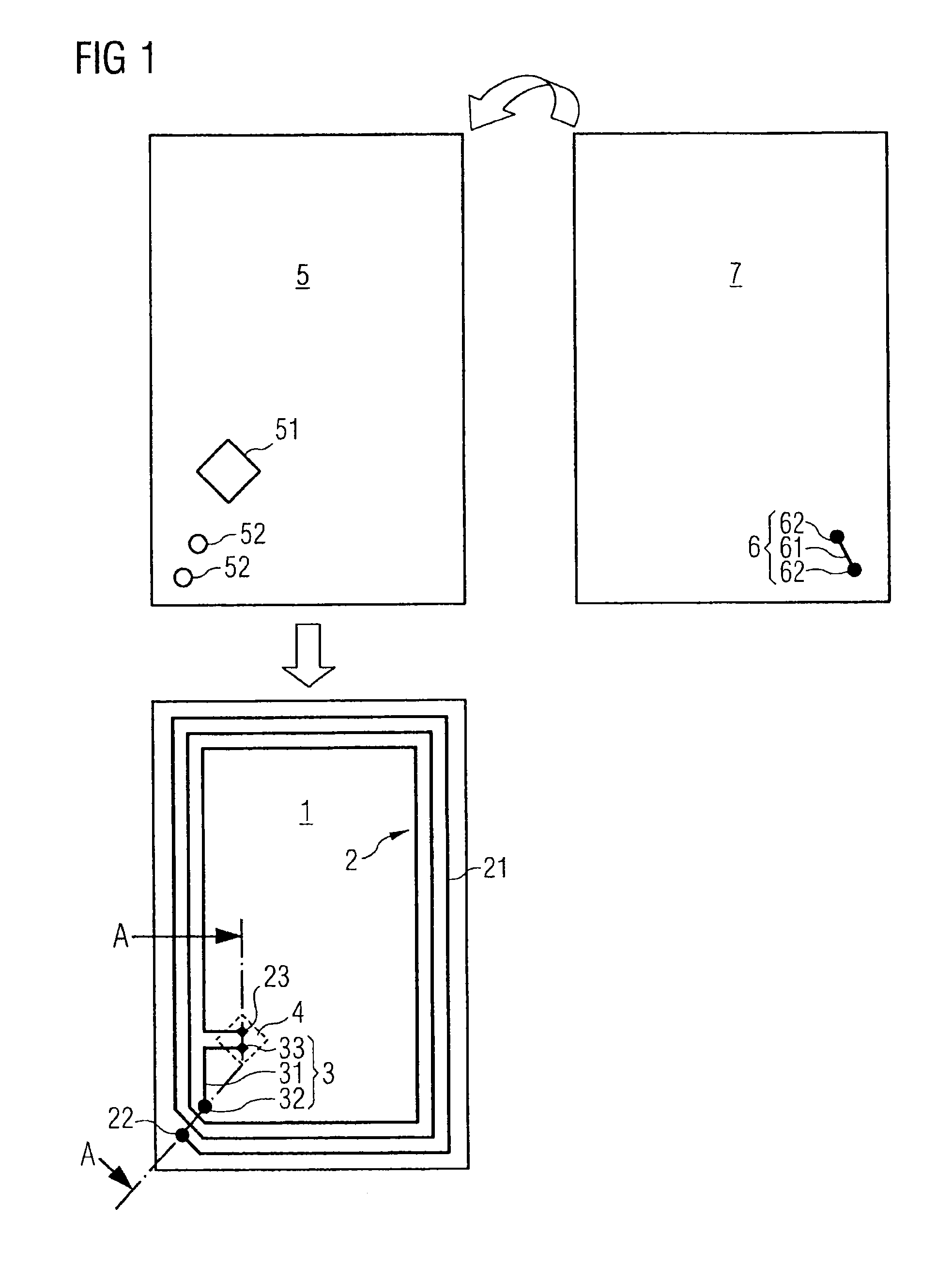
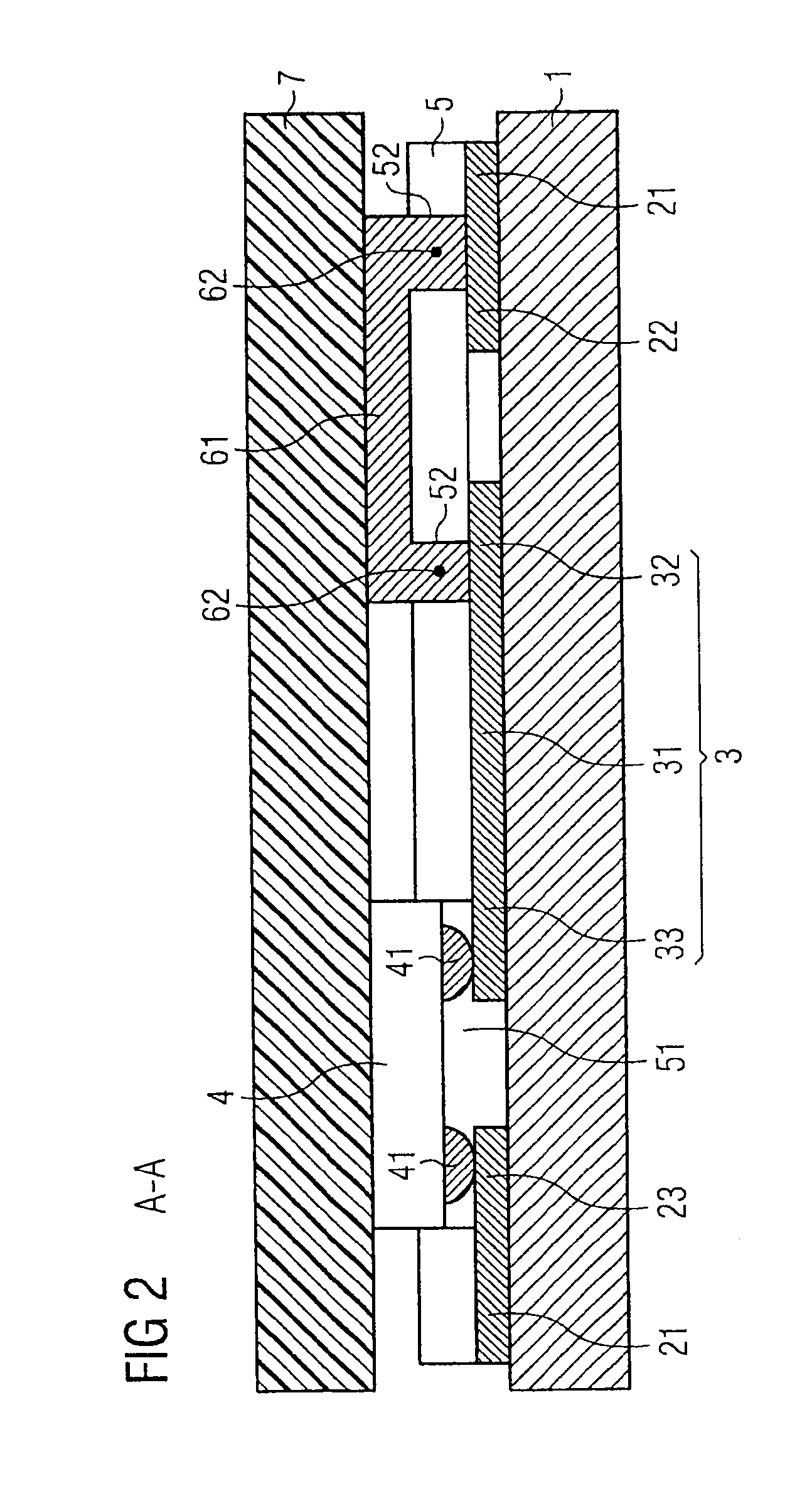
[0041]FIG. 1 shows a carrier layer 1, a compensation layer 5, and a cover layer 7. Arranged on the carrier layer 1, having a continuous surface, are a non-intersecting coil-shaped antenna structure 2 with coil windings 21, a chip terminal 23, and a bridge terminal 22 as well as a connecting structure 3 with a conductor line 31, a chip terminal 33, and a bridge terminal 32.

[0042]A naked chip 4 is placed on the chip terminal 23, 33 of the antenna structure 2 and the connecting structure 3 in the flip-chip technology and contacted.

[0043]A bridge structure 6 with two connector terminals 62 is arranged on the cover layer 7, wherein the connector terminals 62 of the bridge structure 6 may comprise a greater thickness than the conductor line 61 extending between them. The cover layer 7 is shown upside down; therefore the arrangement of the bridge structure 6 seems mirrored compared to the arrangement of the contacting openings 52 on the compensation layer 5 and the bridge terminals 22, 32 ...


PUM


Abstract

A method is provided for producing an arrangement, which, for example, may be used for further processing into a non-contact chip card or an identification document and which comprises a multi-layer structure, with a first part of an RFID antenna, at least comprising a coil-shaped antenna structure and a connecting structure, being arranged on a carrier layer and the chip being directly mounted on this part of the antenna structure and contacted, with a compensation layer being arranged thereabove, which in the area of the chip comprises an embedding opening and which comprises at least two contacting openings in the intersection area of the first part of the RFID antenna with a bridge structure, which is located on a cover layer, and subsequently the individual layers being connected to each other via lamination.

Description

CROSS REFERENCE TO RELATED APPLICATIONS[0001]This application is a national stage filing under section 371 of International Application No. PCT / EP2009 / 064548 filed on Nov. 3, 2009, and published in German on Jun. 3, 2010 as WO 2010 / 060755 and claims priority of German application No. 10 2008 055 630.0 filed on Nov. 3, 2008, the entire disclosure of these applications being hereby incorporated herein by reference.BACKGROUND ART[0002]The invention relates to a method for producing an RFID transponder product and RFID transponder products produced according to said method. Here, an RFID transponder product shall be understood as a circuit arrangement having at least one transponder antenna and at least one integrated circuit (also called “chip” in the following) connected to the transponder antenna (in the following also called “antenna structure”), which is embodied for a wireless data transmission to appropriate readers. Typical examples for such planar RFID transponder products are ...

Claims


Application Information

Patent Timeline
IPC IPC(8): G06K19/02
CPCG06K19/07722G06K19/07749G06K19/07779G06K19/07783H01L23/49855H01L21/56H01L2224/73253H01L2223/6677H01L2224/16225G06K19/077H01L23/485
Inventor WAGNER, MARCOPRESCHER, HENRY
Owner LINXENS HLDG SAS
Why Eureka
Try Eureka