Method for plausibilizing a rail pressure sensor value

Inactive Publication Date: 2014-07-31
ROBERT BOSCH GMBH
View PDF10 Cites 5 Cited by
  • Summary
  • Abstract
  • Description
  • Claims
  • Application Information

AI Technical Summary

Benefits of technology

[0014]The example method according to the present invention can be realized as a computer program and can be stored on a machine-readable carrier that the control device can r

Problems solved by technology

In addition, there exist so-called rail pressure sensor offset tests, which however have the disadvantage that a plausibilization is possible only at the zero point of the rail pressure sensor characteri

Method used


Image

  • Method for plausibilizing a rail pressure sensor value
  • Method for plausibilizing a rail pressure sensor value
  • Method for plausibilizing a rail pressure sensor value

Examples


Example

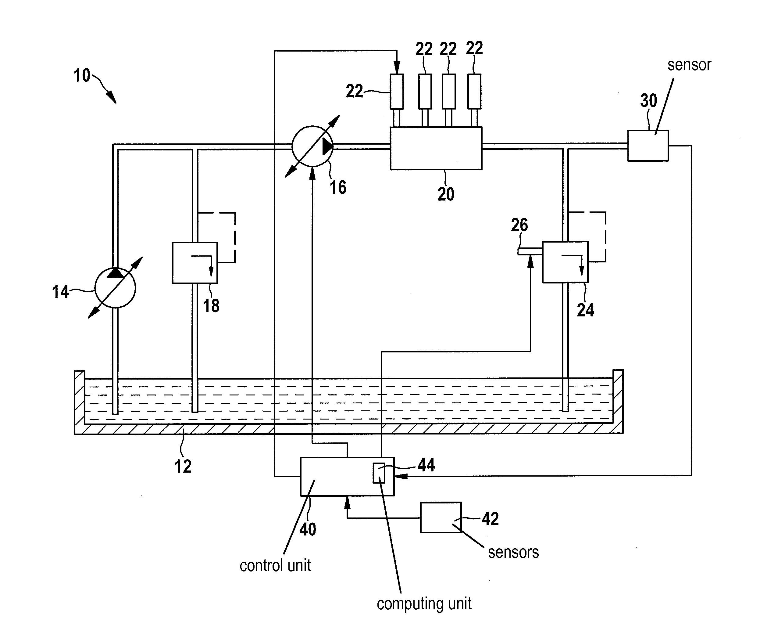
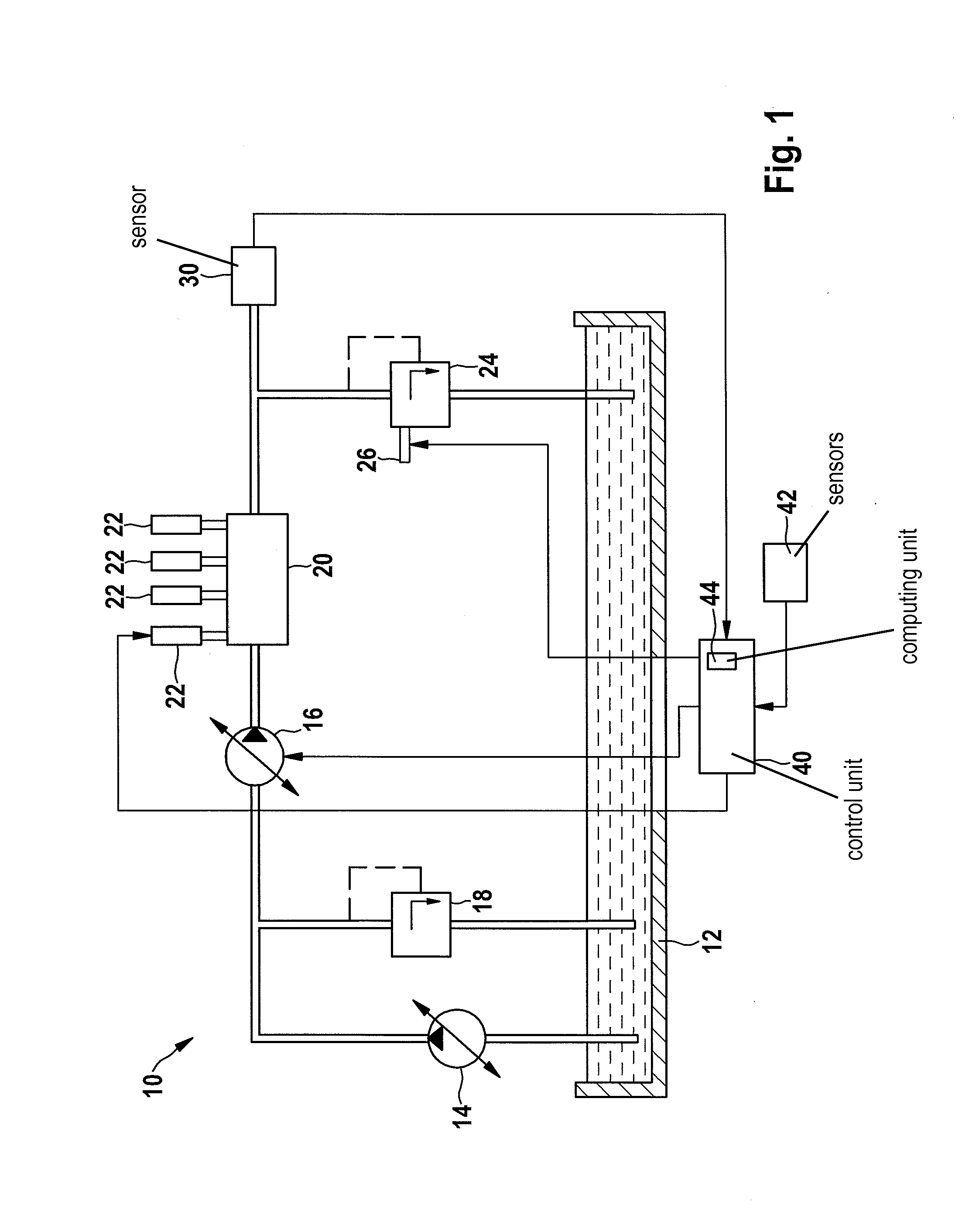
[0019]FIG. 1 shows, in a schematic representation, a fuel supply system 10 that is used in an internal combustion engine. The figure shows a fuel container 12, a pre-conveyor pump 14, a high-pressure pump 16, a low-pressure limiting valve 18, a fuel storage device 20 that is connected to various injectors 22, and a pressure regulating valve 24 via which fuel storage device 20 is connected to fuel container 12. Pressure regulating valve 24 can be controlled by a coil 26, and as a rule is constructed in such a way that, when it receives a control signal, it maintains a particular pressure in fuel storage device 20 and drains unneeded fuel into fuel container 12.

[0020]The lines between the output of high-pressure pump 16 and the input of pressure regulator valve 24 are designated the high-pressure region. In this region, the fuel is under high pressure. A sensor 30 is used to acquire the pressure in the high-pressure region. The lines between fuel container 12 and high-pressure pump 16...


PUM


Abstract

A method for plausibilizing a rail pressure sensor value of a rail pressure sensor of an internal combustion engine having a common rail system that has a fuel high-pressure piston delivery pump includes acquisition of the beginning of conveying by the piston delivery pump, calculation of the rail pressure from the compression work performed by the piston, and plausibilization of the rail pressure outputted by the rail pressure sensor on the basis of the calculated rail pressure.

Description

CROSS REFERENCE[0001]The present application claims the benefit under 35 U.S.C. §119 of German Patent Application No. DE 102013201576.3 filed on Jan. 31, 2013, which is expressly incorporated herein by reference in its entirety.FIELD[0002]The present invention relates to a method for plausibilizing a rail pressure sensor value of a rail pressure sensor of an internal combustion engine having a common rail system, having a camshaft-driven fuel high-pressure piston delivery pump. The subject matter of the present invention also relates to a computer program and a computer program product suitable for carrying out the method.BACKGROUND INFORMATION [0003]Modern diesel engines today standardly have so-called common rail systems that make it possible to inject the fuel into the combustion chambers of the internal combustion engine with very high precision under very high pressures. These common rail systems have rail pressure sensors that acquire the pressure in the rail. The pressure is ...

Claims


Application Information

Patent Timeline
IPC IPC(8): F02D41/14
CPCF02D41/1406F02D41/0097F02D41/123F02D41/0025F02D2041/223F02D2200/0602F02D2200/0604F02D41/222Y02T10/40
Inventor HILLENBRAND, TOBIAS
Owner ROBERT BOSCH GMBH
Why Eureka
Try Eureka