
Home Network System

a home network and home network technology, applied in the field of home network systems, can solve the problems of increasing costs, not being able to install an additional modem inside a manufactured electric device, and not being able to interconnect home appliances

Inactive Publication Date: 2008-10-02
LG ELECTRONICS INC
View PDF14 Cites 1 Cited by
  • Summary
  • Abstract
  • Description
  • Claims
  • Application Information

AI Technical Summary

Benefits of technology

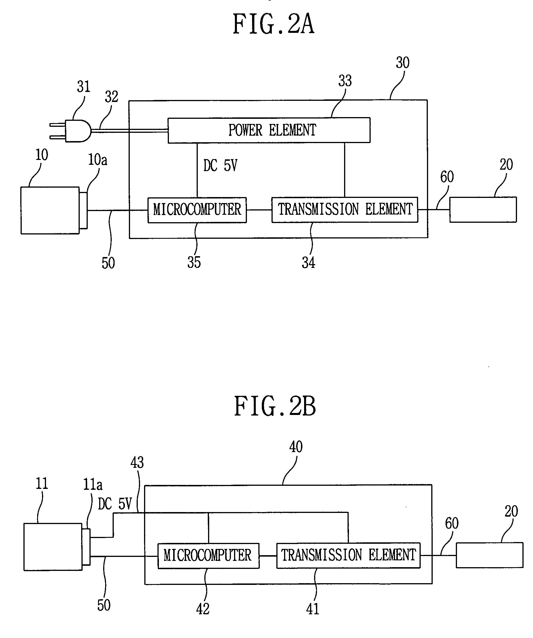
[0028]The object of the present invention is to provide a home network system using a modem having an independent built-in power element that does not require additional wirings or plug outs.
[0029]Another object of the present invention is to provide a home network system in which various modems corresponding to the kind of the transmission lines can be connected to the electric device without affecting electric power consumption of the electric device connected to the modem.
[0030]Another object of the present invention is to provide a home network system using a modem that processes data by itself without increasing load of data being processed by the electric device.

Problems solved by technology

At its early step, the home automation was able to separately control each home appliance by using a telephone or infrared rays, but it was not possible to interconnect the home appliances.
In addition, it is not possible to install an additional modem inside a manufactured electric device.
Because such a data processing increases the load of data to be processed by the electric device, it is necessary to enhance capability of a microcomputer of electric device at the time of manufacturing in order to handle the load of data, so that cost comes to increase.
In addition, such a modem has a disadvantage that it is supplied with electric power and receives data from outside and continues to transmit them to the electric device even when the electric device connected with the modem is out of order and therefore data processing and communications are not possible.
Such a home code establishment problem may bring about bigger problem relating to use of the electric devices and security of the house.
In addition, the problems disclosed in the description about FIG. 3A may also occur at the method in FIG. 3B.

Method used


Image

  • Home Network System
  • Home Network System
  • Home Network System

Examples


Embodiment Construction

[0053]The embodiments of the present invention to realize the objects stated above will now be described in detail with reference to the accompanying drawings and figures.

[0054]FIGS. 4A and 4B are block diagrams of the first and the second embodiments of a home network system according to the present invention.

[0055]Shown in FIG. 4A, a home network system comprises a slave device 12 that carries out its specific function; a master device 20 that communicates with the slave device 12 to control and / or monitor the state thereof; and a modem 70 that is mounted on the slave device 12 and makes the slave device 12 to communicate with the master device 20.

[0056]More particularly, the slave device 12 communicates with the modem 70 through a signal line 50 and comprises a communication interface 13 to transmit external power (AC power) without any conversion through a power line 74 of the modem 70. The modem 70 can be installed in or mounted on the slave device 12. In addition, the modem 70...


PUM


Abstract

The present invention relates to a home system, and more particularly to a home network system that is able to reduce of electric device by application of a modem that is capable of independently processing data. The present invention comprises a first electric device to transmit data including a home code input by the outside to a second electric device through a predetermined network; and a second electric device that comprises a modem by which it is connected to the first electric device through the network, and makes the modem to receive the data, after the initialization of the modem is finished, and read the home code from the data and establish it as its own home code.

Description

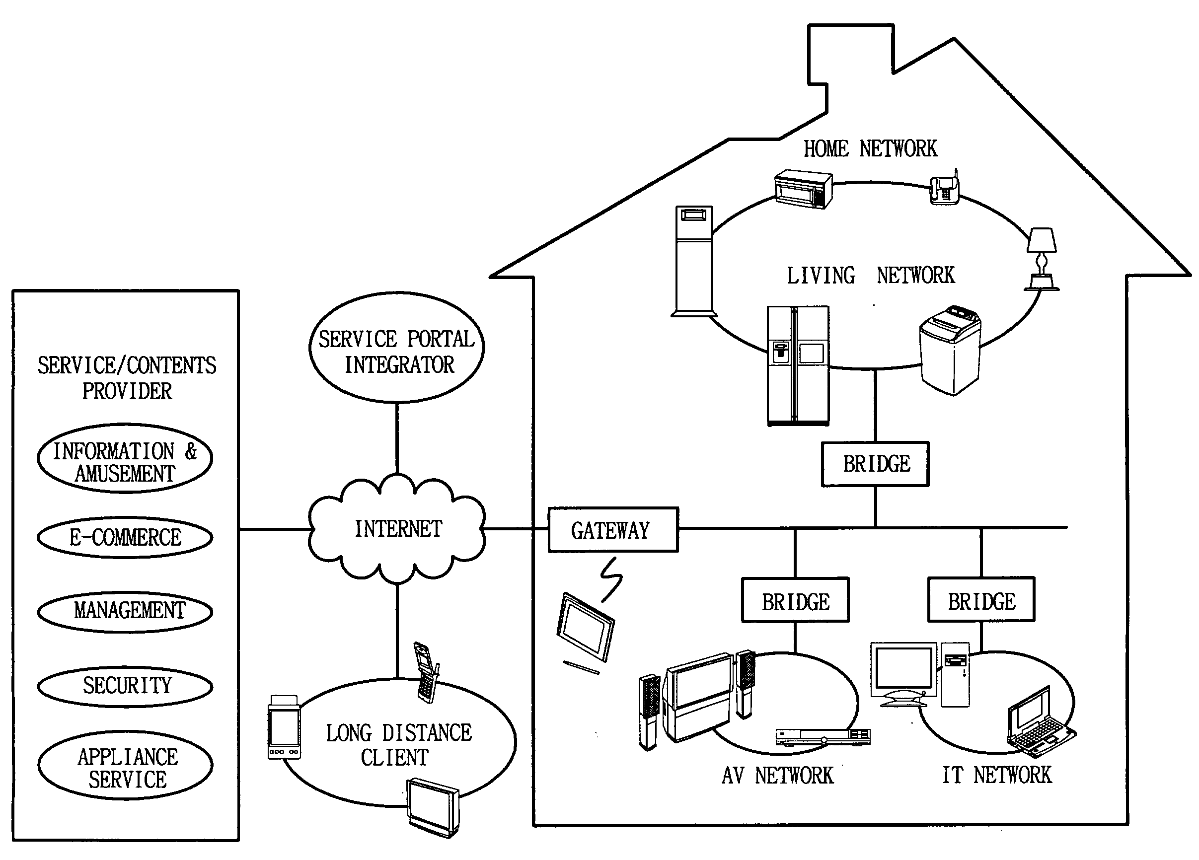
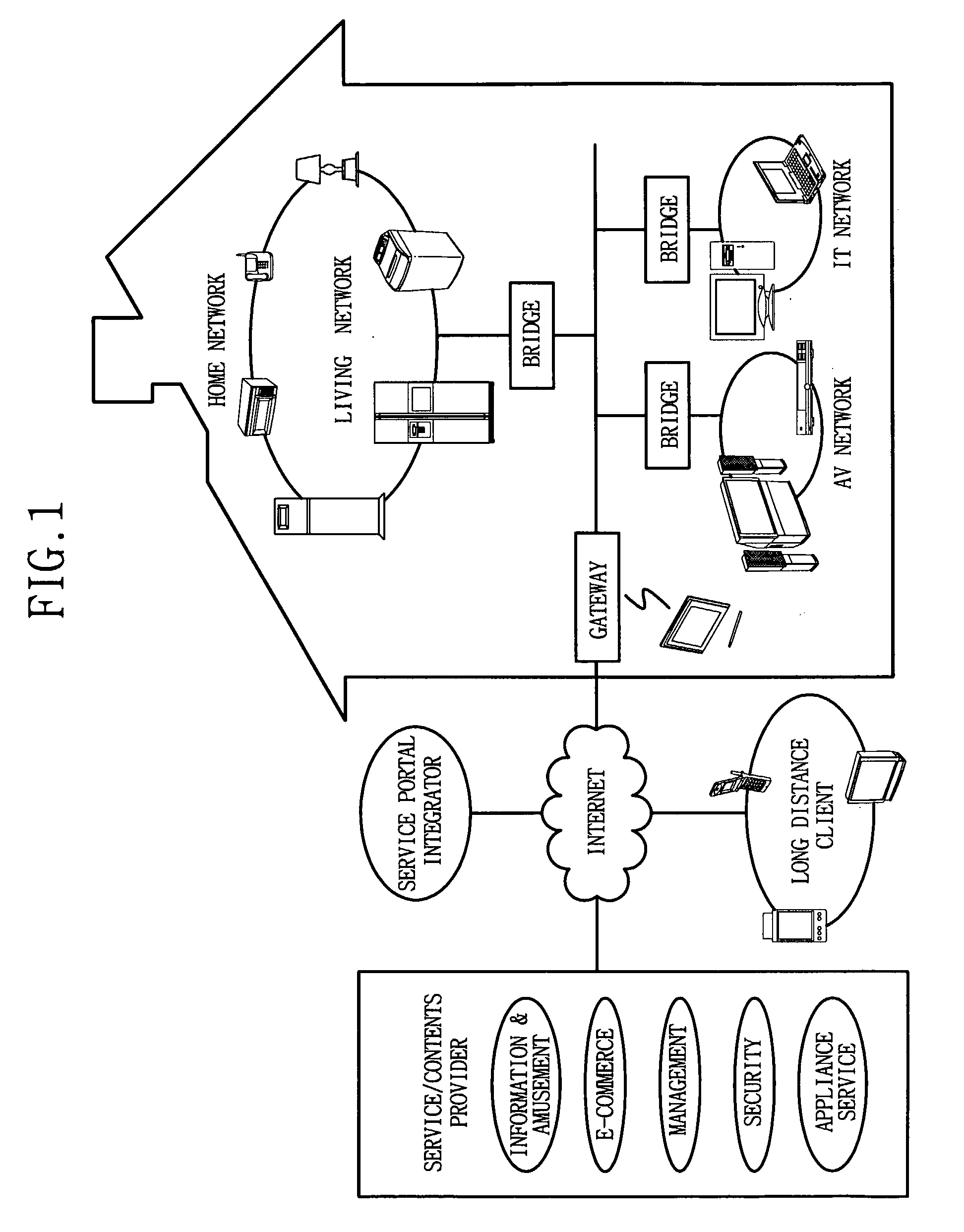
TECHNICAL FIELD[0001]The present invention relates to a home network system, and more particularly to a home network system that is able to reduce loads of electric device by application of a modem that is capable of independently processing data.BACKGROUND ART[0002]At the present day, home automation technology for automatically controlling home appliances at each home or remotely has almost reached a commercialization point. At its early step, the home automation was able to separately control each home appliance by using a telephone or infrared rays, but it was not possible to interconnect the home appliances. However, there has been suggested a method for building a network of home appliances by using a communication means, and collectively controlling the network by using a controller.[0003]FIG. 1 is a block diagram illustrating a general home network system as a whole. Referring to FIG. 1, a home network connects various digital home appliances so that a user can always enjoy ...

Claims


Application Information

Patent Timeline
Patent Type & Authority Applications(United States)
IPC IPC(8): H04B1/38
CPCH04L12/2803H04L12/282H04L2012/2843H04L2012/285
Inventor LEE, KOON-SEOKBAEK, SEUNG-MYUN
Owner LG ELECTRONICS INC
Learn More