Shower head assembly

a shower head and assembly technology, applied in the field of shower head, can solve the problems of extra and unnecessary use of water, inability to adjust the volume of water going through the shower head,

Inactive Publication Date: 2007-12-04
WU JAMES
View PDF8 Cites 117 Cited by
  • Summary
  • Abstract
  • Description
  • Claims
  • Application Information

AI Technical Summary

Problems solved by technology

Although the pattern of water that flows out from the pattern holes 851 can be adjusted, the volume of water going through the shower head cannot be adjusted and this might lead to an extra and unnecessary use of water.

Method used


Image

  • Shower head assembly
  • Shower head assembly
  • Shower head assembly

Examples


Embodiment Construction

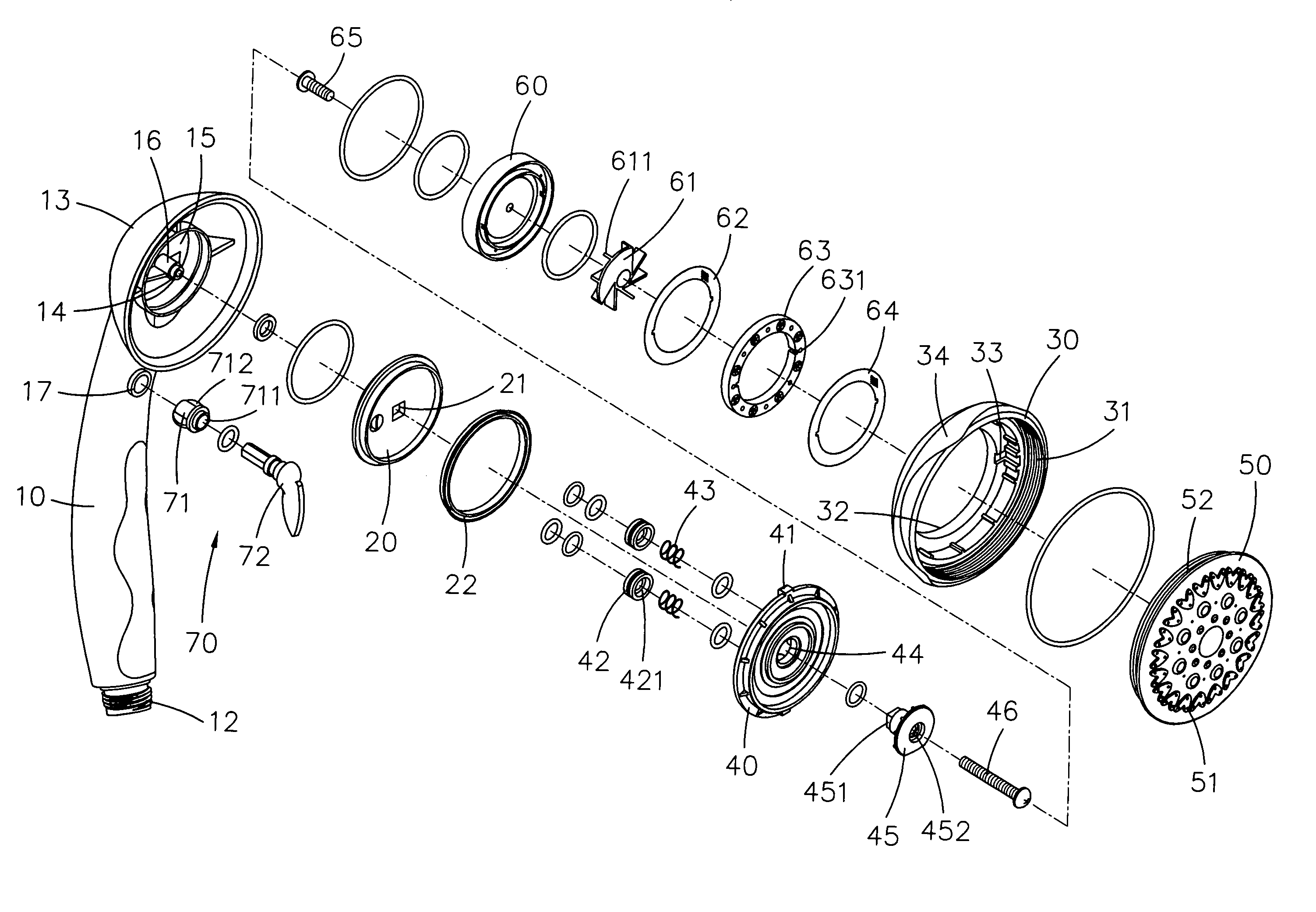
[0012]Referring to FIGS. 3 to 5, the shower head of the present invention comprises a hollow handle 10 and a head 13 connected to an end of the handle 10. A connection end 12 is connected to the other end of the handle 10 so as to be connected to a hose (not shown) through which water enters the hollow handle 10 and flows out from the head 13. A chamber 15 enclosed by a cup or tubular wall 14 is defined in the head 13 and a connection tube 16 extends from a center of the chamber 15. A base plate 20 with a seal 22 mounted to an outside thereof is engaged with the chamber 15 and a rectangular through hole 21 is defined through a center of the base plate 20.

[0013]A rotatable member 30 has a neck portion 32 extending from a first end thereof and two notches 33 are defined in an inner periphery of the rotatable member 30. A fixed plate 40 has two protrusions 41 which are engaged with the notches 33 of the rotatable member 30. Two tubular members 42 are located between the fixed plate 41 ...


PUM


Abstract

A shower head assembly includes a hollow handle and a head. A base plate is engaged with the head and a rotatable member is connected to the head and a fixed plate is secured to the rotatable member. Two tubular members are located between the fixed plate and the base plate. Two springs are received in two respective interiors of the two tubular members and biased between the fixed plate and the base plate. A pattern plate having a plurality of pattern holes is fixed to the rotatable member. A filtering assembly including a cap, an adjusting member with a plurality of ribs, a first filter, a separation ring with a plurality of holes and a second filter. A bolt extends through the filtering assembly and connecting the filtering assembly to the pattern plate. A volume control device is engaged with a connection hole defined through a wall of the handle so as to control water volume through the handle.

Description

FIELD OF THE INVENTION[0001]The present invention relates to a shower head that includes a volume control device for controlling volume of water flowing through the shower head.BACKGROUND OF THE INVENTION[0002]A conventional shower head 80 is shown in FIGS. 1 and 2 and generally includes a handle 81 and a head 811 is connected to an end of the handle 81. The head 811 includes a tubular chamber 812 therein and a connection tube 813 extends from an inside of the head 811. A fixed plate 82 is fixed in the chamber 812 by a screw 822 extending through a washer 823 and a central hole 824 of the fixed plate 82 and threaded connected to the connection tube 813. The fixed plate 82 includes a plurality of outlets 821. A rotatable member 83 is mounted to the fixed plate 82 and a ring 84 is located between the rotatable member 83 and the fixed plate 82. A pattern member 85 is connected to the rotatable member 83 and includes a plurality of pattern holes 851 so that when rotating the rotatable m...

Claims


Application Information

Patent Timeline
Patent Type & Authority Patents(United States)
IPC IPC(8): A62C31/00
CPCB05B1/30B05B1/18A62C31/02B05B1/1654B05B3/04
Inventor WU, JAMES
Owner WU JAMES
Why Eureka
Try Eureka