Ergonomic wheelchair hand rim

Inactive Publication Date: 2007-12-04
RICHTER WILLIAM MARK +2
View PDF16 Cites 20 Cited by
  • Summary
  • Abstract
  • Description
  • Claims
  • Application Information

AI Technical Summary

Benefits of technology

[0014]The present invention is distinguished over the known prior art in a multiplicity of ways. One embodiment of the invention provides an ergonomic hand rim device and its method of use for a manual wheelchair, comprised of an expanded and more ergonomically contoured grip surface to reduce peak pressure on the hand thereby improving comfort during use. The ergonomic hand rim device also provides improved frictional characteristics over a portion of the grip surface without compromising braking performance. Because of the increased frictional characteristics, the user does not need to grip as hard when pushing the wheelchair. Additionally, the ergonomic hand rim device reduces impact loading both locally between the hand and the hand rim as well as generally between the hand rim and a wheelchair wheel.
[0015]In one embodiment of the invention, the ergonomic hand rim device and its method of use is comprised of a contoured elastomeric interface, operatively coupled between an upper inboard portion of a tubular hand rim and a wheel rim of a wheelchair wheel for, among other things, replacing the rigid and discrete attachment mechanism commonly used to attach the standard hand rim to the wheelchair wheel rim. When pushing, the user grips across both the tubular hand rim and the contoured elastomeric interface. When braking for an extended period of time, the user only grips the tubular hand rim, thereby preventing burning of the hands. The contoured elastomeric interface provides benefits in hand rim shape, friction, and impact attenuation.
[0016]More particularly, and in one embodiment of the invention, the ergonomic hand rim device is comprised of a circular heat conducting tubular hand rim having a diameter less than a wheel rim of a wheelchair and spaced outboard of the wheel by a circumferential continuous elastomeric interface with a cross-sectional contour that includes an outwardly extending member having a generally convex shape, a concave upper surface immediately adjacent to the wheel rim, and a recessed lower surface and having a proximal end operatively coupled to an outboard side of the wheel rim and transitioning into and integrally formed with a downwardly depending member terminating to a distal end operatively coupled to an inboard upper portion of the tubular hand rim. A majority of the tubular hand rim is exposed and devoid of the elastomeric interface, such that under sustained braking only the heat conducting tubular hand rim is used. When pushing, the user grips across both the tubular hand rim and the contoured elastomeric interface, which generally matches the shape of the hand. The contoured elastomeric interface deforms under slight grip pressure to further improve fit with each specific hand shape, thereby improving comfort as well as frictional coupling to the hand during use. As a result, the user does not need to grip as hard when pushing. Impact loading is reduced locally between the hand and the hand rim as the elastomeric interface deforms under the hand during propulsion. Impact is further reduced generally between the hand rim and the wheel rim as the elastomeric interface deforms and the tubular hand rim displaces relative to the wheel rim.

Problems solved by technology

Since wheelchair users rely on their upper extremities for mobility, pain and injuries to the upper extremity can severely impact function and independence.
Unfortunately, there is a high occurrence of upper extremity repetitive stress injuries in the manual wheelchair user population.
While generally suitable for propelling and maneuvering the wheelchair, conventional hand rims have some inherent disadvantages.
For many users, this level of pressure against the hands may be uncomfortable or even painful.
Hand rims are generally smooth with poor frictional properties.
Unfortunately, since the high friction coatings are heat insulators they result in a rapid local heat buildup at the hand / hand rim interface, making them unsuitable for sustained braking.
While these designs may serve to improve manufacturability, they do not address the ergonomic disadvantages of the standard hand rim.
While improvements in grip comfort are important, these designs do not address the issues of low friction and impact loading during use.
While all of these designs attempt to improve frictional characteristics for pushing, they do not reduce impact loading during propulsion.
Since the top surfaces of the hand rims have a high friction heat insulating coating, the user cannot grip on the top surface when braking.
Instead, the user must pull up on the bottom surface of the hand rim, which is more difficult to do and control than the standard braking technique.
While this design addresses the target ergonomic issues, there are some disadvantages, including: 1) in order to reduce the impact, which occurs locally between the hand and the hand rim, the entire hand rim must displace relative to the wheel rim, 2) the frictional benefits rely on the use of the dual-hand rim system, which requires two hand rims, equating to additional weight and cost, and 3) the shape of the handrim does not conform to the shape of the hand when gripped, resulting in peak pressure points on the hand during use.

Method used


Image

  • Ergonomic wheelchair hand rim
  • Ergonomic wheelchair hand rim
  • Ergonomic wheelchair hand rim

Examples


Embodiment Construction

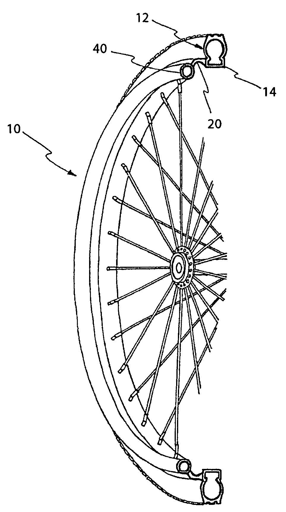
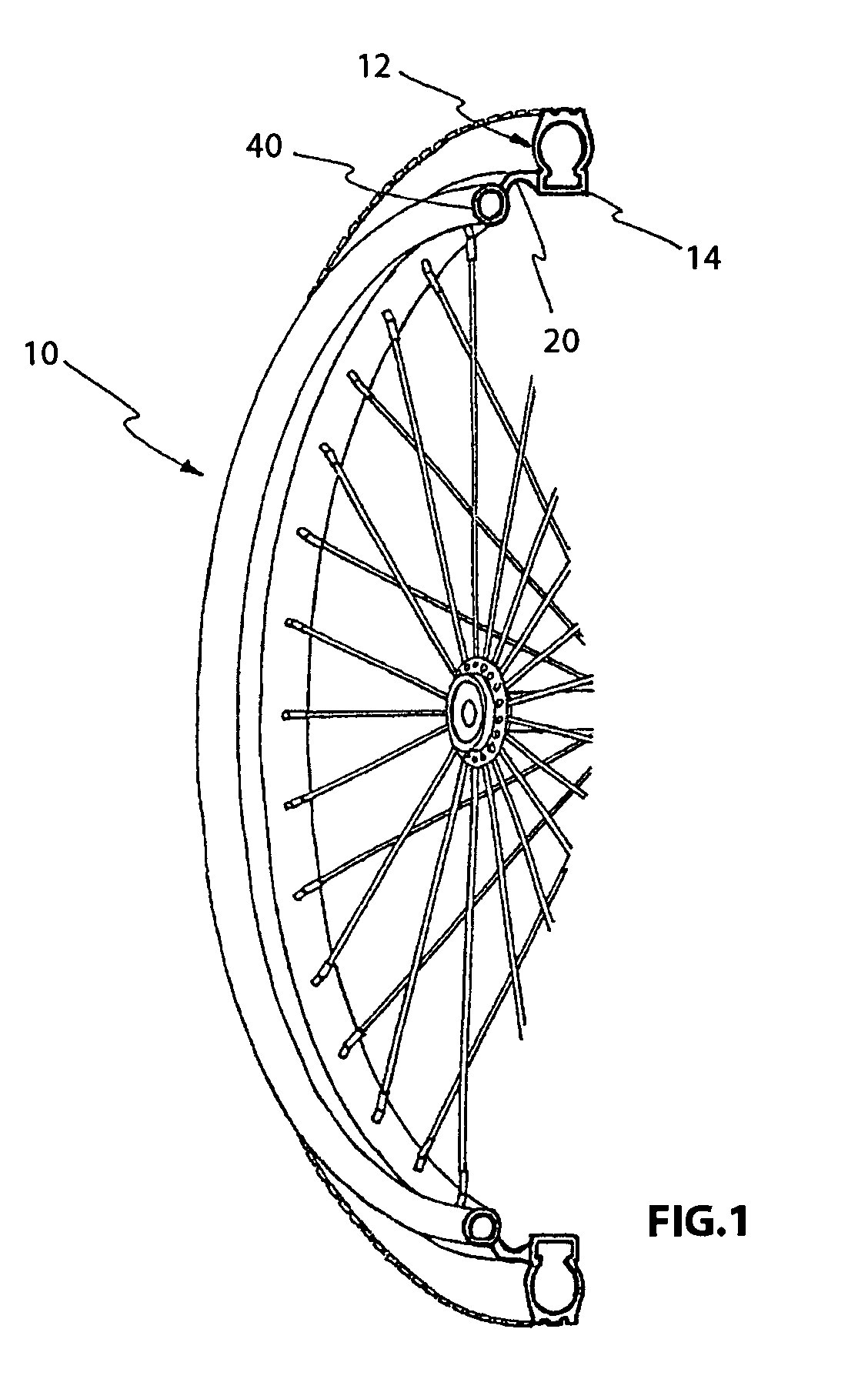
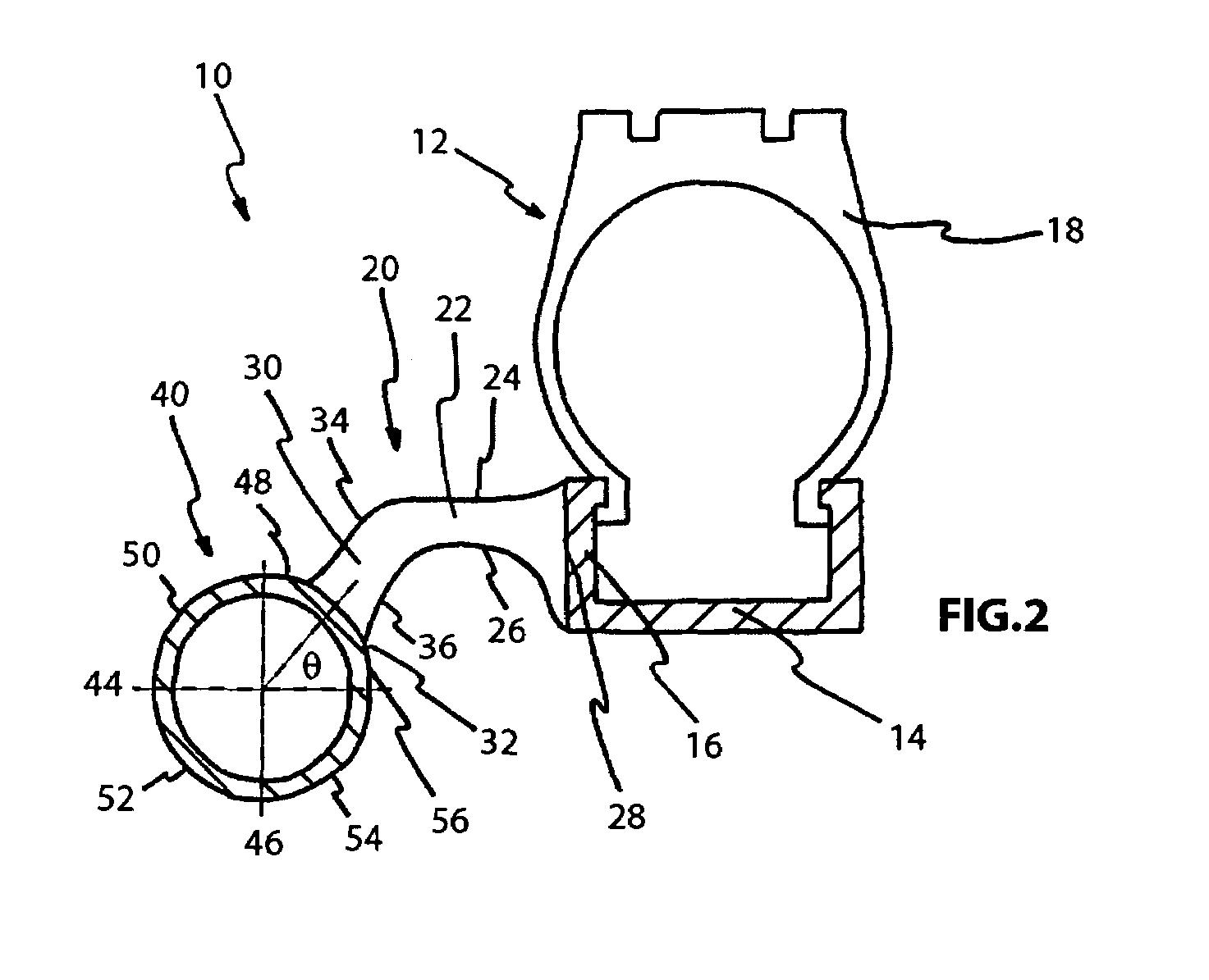
[0031]Considering the drawings, wherein like reference numerals denote like parts throughout the various drawing figures, reference numeral 10 is directed to an ergonomic hand rim device for a manual wheelchair.

[0032]In its essence, and referring to the drawings, an embodiment of this invention provides an ergonomic hand rim device 10 for a manual wheelchair wheel 12 comprised of a wheel rim 14 including an outboard side 16 and having a tire 18 mounted thereon as illustrated in FIGS. 1 and 2. The ergonomic hand rim device 10 is comprised of a circular heat conducting tubular hand rim 40 and a continuous contoured elastomeric interface 20 spanning and operatively coupled between an upper inboard side or portion 32 of the circular heat conducting tubular hand rim 40 and the outboard side 16 of the wheel rim 14 as illustrated in FIGS. 1 through 13 such that when gripped by a hand of a user pushing forward the continuous contoured elastomeric interface 20 deforms to the hand of the user...


PUM


Abstract

Wheelchair hand rim device comprised of a heat conducting tubular hand rim and a continuous circumferential elastomeric interface that has a cross-sectional contour comprised of an outwardly extending horizontal member having a proximal end coupled to an outboard side of a wheel rim transitioning into a downwardly depending member terminating to a distal end coupled to an inboard upper portion of the tubular hand rim such that a majority of the tubular hand rim is exposed and devoid of the elastomeric interface. When braking, a user only uses the heat conducting tubular hand rim. When pushing, the user grips across both the tubular hand rim and the contoured elastomeric interface, which deforms to fit the hand, thereby providing improved comfort, frictional coupling, and impact attenuation.

Description

STATEMENT REGARDING FEDERALLY SPONSORED RESEARCH OR DEVELOPMENT[0001]This invention was developed with government support under SBIR Phase II Grant #2 R44 HD36533-02A2 by the National Center for Medical Rehabilitation Research in the National Institute of Child Health and Human Development at the National Institutes of Health. The government has certain rights in the invention.FIELD OF THE INVENTION[0002]This invention relates generally to wheelchair hand rims, and in particular, to an ergonomic wheelchair hand rim device and its method of use for a manual wheelchair.BACKGROUND OF THE INVENTION[0003]The manual wheelchair user controls the wheelchair with the hand rims. The wheelchair hand rim is typically a tubular hoop rigidly attached to the outside of the wheel. The hand rim, or handrim is known by several different names, including pushrim, handring, and handrail. Most hand rims in use today are made from steel or aluminum tubing that has been formed into a hoop with the ends we...

Claims


Application Information

Patent Timeline
IPC IPC(8): B62M1/14A61G5/02A61G5/10
CPCA61G5/028A61G5/02B33Y80/00
Inventor RICHTER, WILLIAM MARKNOON, JAMIE HAMEEDAXELSON, PETER WILLIAM
Owner RICHTER WILLIAM MARK
Why Eureka
Try Eureka