Backrest adjusting device for office chairs

a technology for adjusting devices and chairs, which is applied in the direction of adjustable chairs, chairs, transportation and packaging, etc., can solve the problems of occupying a large storage space, affecting the overall stylish look, and the conventional fixed headrest violates these principles, so as to achieve the best attaching angle

Inactive Publication Date: 2007-12-04
CHEN YUNG HUA
View PDF11 Cites 113 Cited by
  • Summary
  • Abstract
  • Description
  • Claims
  • Application Information

AI Technical Summary

Benefits of technology

[0007]It is a primary object of the invention to provide a backrest adjusting device for office chairs, such that the three-dimensional space including position, height, longitudinal buffer and angular rotation of a backrest or a headrest can be adjusted according to a user's type of build, need and feel to improve the effect of achieving the best attaching angle.

Problems solved by technology

However, a problem of such structure resides on that the best leaning angle of a person's neck varies with each person's type of build, need and feel, when the person is sitting on a chair.
Obviously, the design of the conventional fixed headrest violates these principles and definitely does not comply with practical applications.
Since the driving position is situated at a lateral side of the backrest 53, the actual installation and operation of the chair greatly affect the overall stylish look of the chair, and the detached parts occupy much storage space when they are not in use.
Further, the extensible and displaceable backrest bump 56 installed in the backrest cannot achieve the effect of supporting a user's waist or providing the elasticity for the backrest bump 56 due to the limitation by a too small driving extension and displacement.
Further, the extensible and displaceable backrest bump 56 installed in the backrest 53 requires an extra transmission module to drive a stand board in the backrest 53 for the extension and displacement, and such arrangement incurs additional component and installation costs.

Method used


Image

  • Backrest adjusting device for office chairs
  • Backrest adjusting device for office chairs
  • Backrest adjusting device for office chairs

Examples


Embodiment Construction

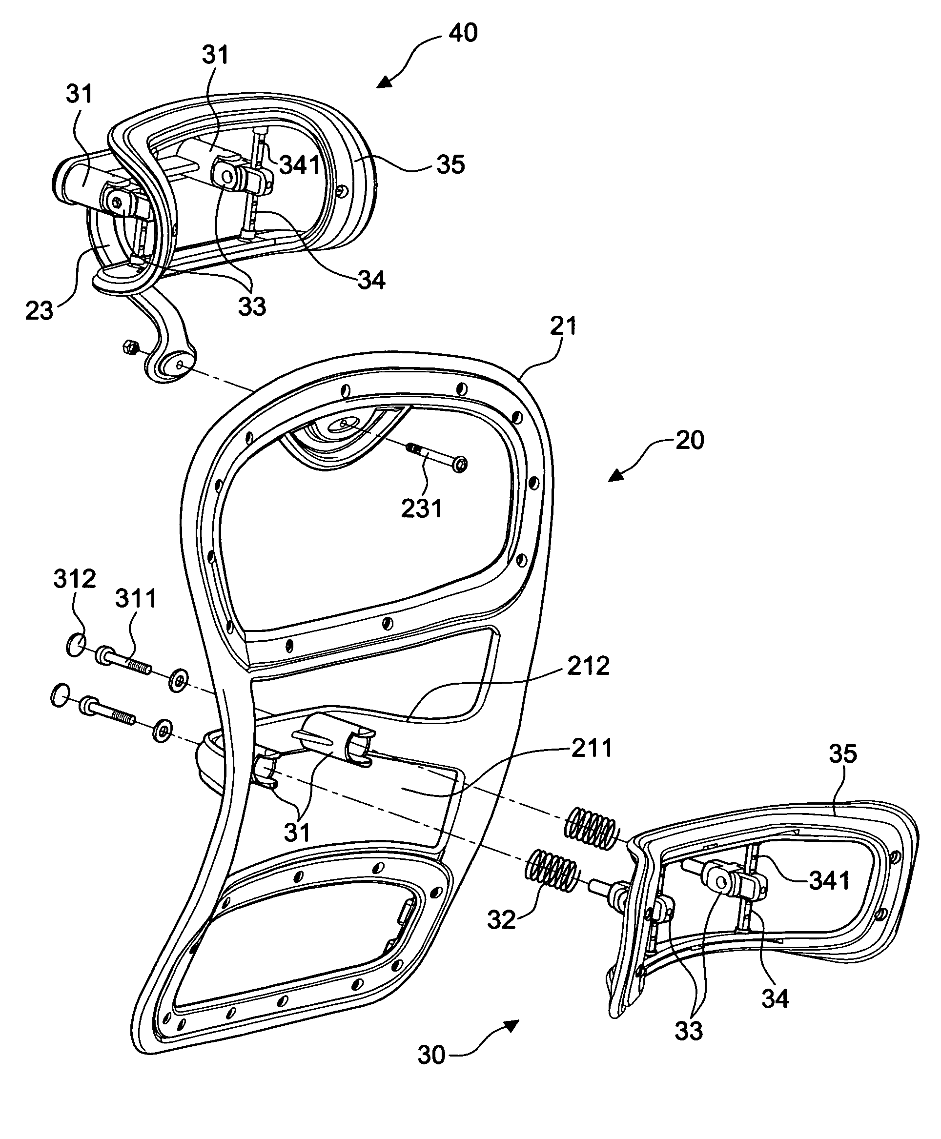
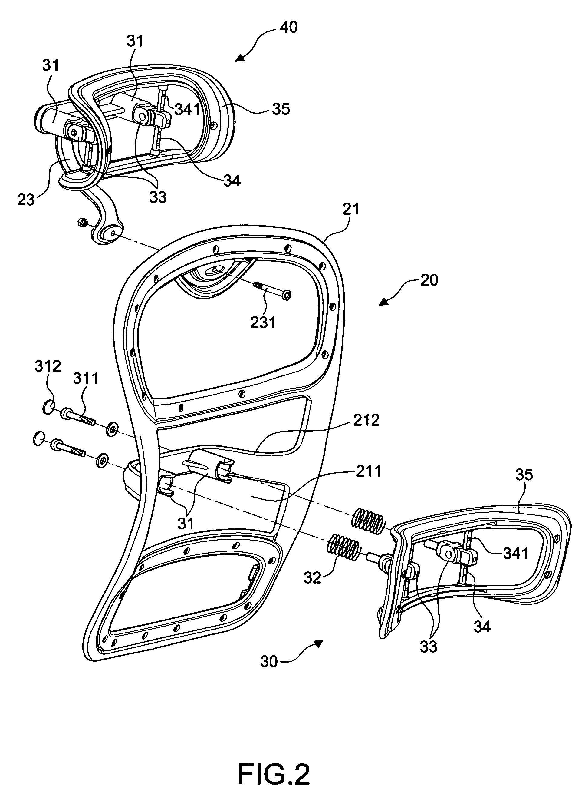
[0027]Referring to FIGS. 2 and 3 for an exploded view and a perspective view of a backrest of the present invention, a back20 includes a frame 21, a back cushion 24 fixed onto a surface of the frame 21 as shown in FIG. 8, a connecting member 22 installed at a rear side of the seat portion 10 for connecting the bottom of the back 20, a hollow containing space 21 disposed at the middle section of the back 20, an n-shaped member 211 disposed in the containing space and extended backward, and a first attaching device 30 installed on an n-shaped member 211 of the containing space for adjusting the height, longitudinal buffer and angular rotation of the back 20. Referring to FIG. 4 for a cross-sectional view of the foregoing first attaching device 30, the structure as shown in FIGS. 2 to 4 comprises:

[0028]at least two parallel pipe bodies 31, fixed on an internal side of the n-shaped member 211 with an opening facing upward;

[0029]at least two springs 32, sheathed into each pipe body 31;

[0...


PUM


Abstract

A backrest adjusting device for office chairs comprising: a seat portion having a seat cushion and a stand for supporting the seat cushion; a back having a frame, a back cushion fixed on the surface of the frame, a connecting member for connecting the bottom of the back to a rear side of the seat portion, a hollow containing space formed at the middle section of the back, an n-shaped member being disposed in the containing space and extended backward; and a first attaching device installed on the n-shaped member of the containing space, thereby achieving the adjustment of the three-dimensional space of position, longitudinal buffer and angular rotation. Moreover, the back further includes a support member disposed at the top of the back, and a second attaching device installed on the support member and having a structure identical to the first attaching device. Meanwhile, the first attaching device has an attaching body made in compliance with the shape of a human waist to form a backrest bump. Furthermore, the second attaching device has an attaching body made in compliance with the shape of a human head to form a headrest. In this way, the three-dimensional space such as position, height, longitudinal buffer and angular rotation of a backrest or a headrest is adjustable.

Description

BACKGROUND OF THE INVENTION[0001]1. Field of the Invention[0002]The present invention relates to a backrest adjusting device for office chairs, and more particularly to a novel spatial design for a backrest and a headrest with the features of adjustable height, longitudinal buffer and angular rotation.[0003]2. Description of the Related Art[0004]Referring to FIG. 1 for a conventional office chair, the chair includes a stand 51 having a plurality of rollers, a seat cushion 52 fixed by an erected support rod, a backrest 53 installed vertically at the rear end of the seat cushion 52, and an arc streamlined headrest 55 pivotally connected to the backrest 53 by a plurality of insert rods 54. The height of the headrest 55 can be adjusted by fixing the positions of the insert rods 54 and the backrest 53. However, a problem of such structure resides on that the best leaning angle of a person's neck varies with each person's type of build, need and feel, when the person is sitting on a chair...

Claims


Application Information

Patent Timeline
Patent Type & Authority Patents(United States)
IPC IPC(8): A47C7/46A47C7/38
CPCA47C7/38A47C7/462A47C7/405
Inventor CHEN, YUNG-HUA
Owner CHEN YUNG HUA
Why Eureka
Try Eureka