Device for supplying an electro-pen with electrical energy

Inactive Publication Date: 2007-12-04
SYNTHES USA
View PDF13 Cites 1189 Cited by
  • Summary
  • Abstract
  • Description
  • Claims
  • Application Information

AI Technical Summary

Benefits of technology

[0014]As previously described, the console is configured to be liquid-tight in order to ensure that it can be sterilized and is re

Problems solved by technology

Electro-pens known according to the aforementioned state of the art have the disadvantage that the energy supplying console with energy supply u

Method used


Image

  • Device for supplying an electro-pen with electrical energy
  • Device for supplying an electro-pen with electrical energy

Examples


Embodiment Construction

[0017]For convenience, the same or equivalent elements in various embodiments of the invention illustrated in the drawings have been identified with the same reference numerals. Further, in the description that follows, any reference to either orientation or direction is intended primarily for the convenience of description and is not intended in any way to limit the scope of the present invention thereto.

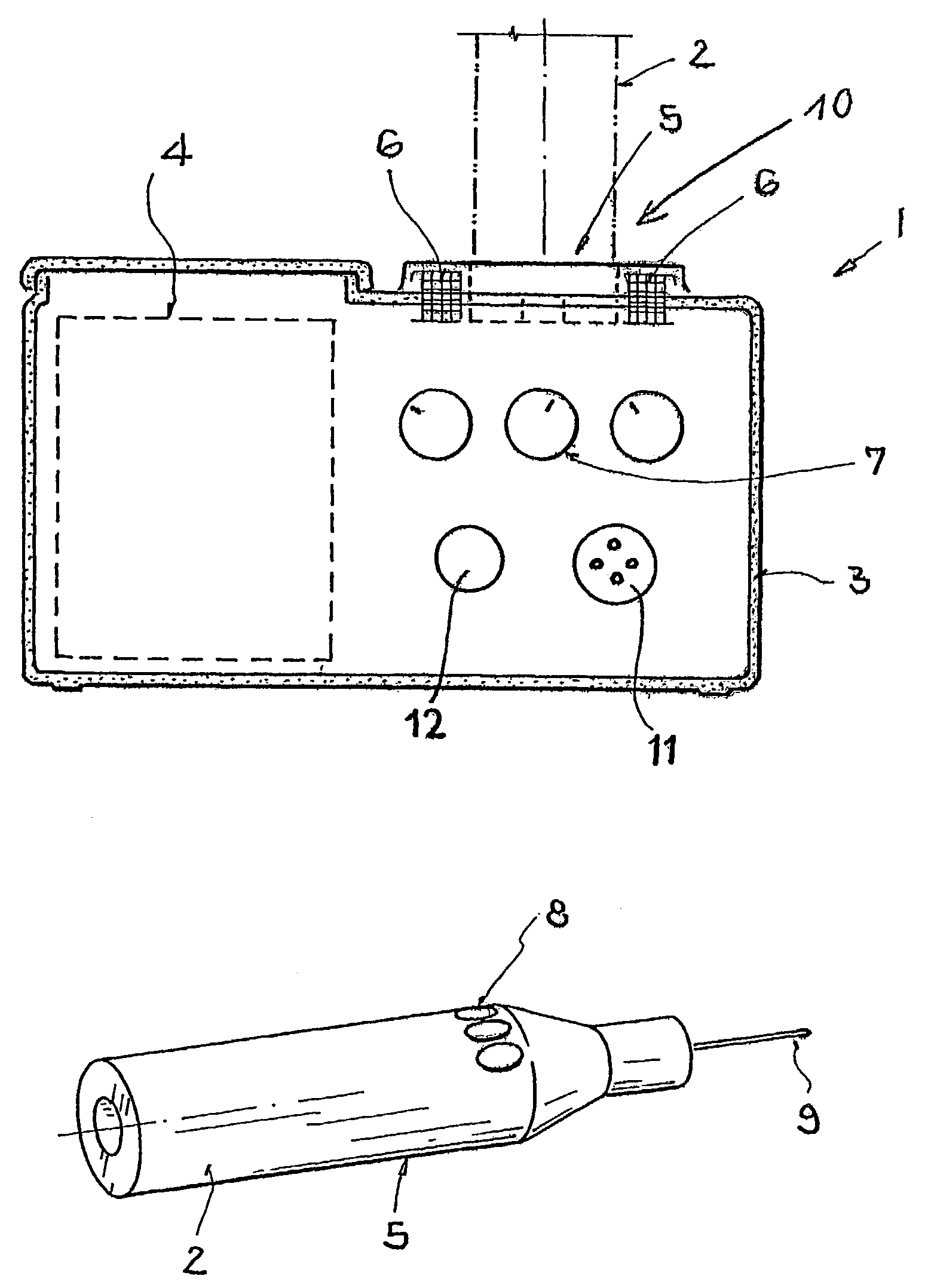
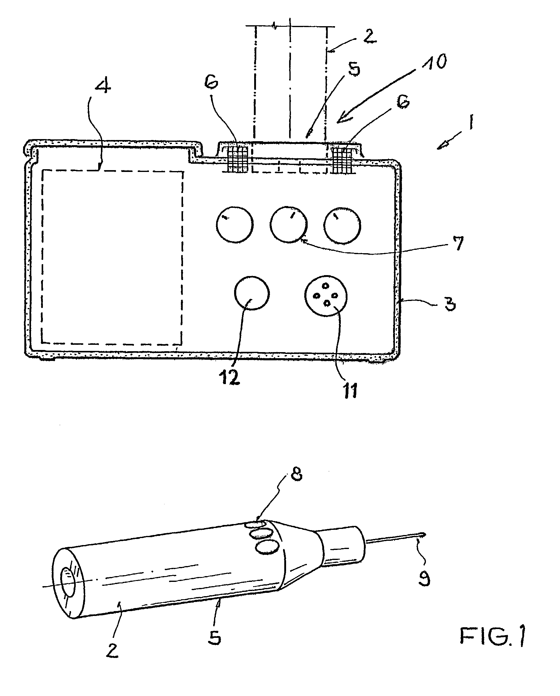
[0018]FIG. 1 shows a preferred embodiment of the electrical energy supplying device according to the present invention. The device for supplying an electro-pen with electrical energy comprises a console with an energy supply unit 1 having operating elements 7 as well as an electro-pen 2 having operating elements 8. The electro-pen 2 is supplied with electrical energy either directly via an electrical cable or indirectly via induction through electrical contacts and a small energy storage device, which will be discussed in greater detail below. The electro-pen 2 is equipped with an ...


PUM


Abstract

The invention relates to a device for supplying electrical energy to an electro-pen with an electric drive unit for driving a tool. The device comprises a console with an energy supply unit having an accumulator for supplying the electrical drive unit with electrical energy. The console may be configure to be sterilized by steam having a housing and electrical components that are sealed liquid-tight. The accumulator may include a sterile covering for sterile introduction into the console. A coupling between the console and the electro-pen carries the supply of electrical energy from the console to the electro-pen. The coupling may be an electrical contact in the form of a sterilizable connector or an inductive coupling. The console may be configured to store energy and is thus mobile, or the console may include a connection for connecting to a mains or external power supply for charging the accumulator. The console may include a switch-mode power supply for charging the accumulator. The console may include a holder for receiving and charging the electro-pen. The electro-pen includes an electrical storage device and a coupling for receiving the electrical energy supply from the accumulator. The holder may include an electrical coupling between the console and the electro-pen in which at least two electrical contacts and at least one transformer are disposed about each the holder and the electro-pen. Alternatively, the holder may include an inductive coupling in which at least one transformer having at least one coil is disposed about each the holder and the electro-pen.

Description

CROSS-REFERENCE TO RELATED APPLICATIONS[0001]The application is a continuation of the U.S. National Stage designation of copending International Patent Application PCT / CH00 / 00541, filed Oct. 4, 2000, the entire content of which is expressly incorporated herein by reference thereto.FIELD OF THE INVENTION[0002]The invention relates to a device for supplying an electro-pen with electrical energy.BACKGROUND OF THE INVENTION[0003]Devices known in the art which supply electrical energy to an electro-pen are often applied in the medical field, in particular, surgical procedures. Electro-pens are typically used, for example, in operations in the visual and hand area.[0004]Electro-pens, according to the state of the art, consist of a drive unit in the form of a pen, i.e., in the form of a pen holder, an electric cable, and a console which converts the mains voltage into a low voltage suitable for the drive unit.[0005]An electromagnetic pen for the treatment of humans and animals is disclosed...

Claims


Application Information

Patent Timeline
IPC IPC(8): A61B18/14A61B18/04A61M35/00A61N1/18
CPCA61B18/1402A61N1/18A61B2018/1226
Inventor METZGER, ROGER
Owner SYNTHES USA
Why Eureka
Try Eureka