
Front-mountable injection molding nozzle

a front-mounted, nozzle technology, applied in the field of injection molding apparatuses, can solve the problems of more frequent repair and maintenance, and achieve the effect of good sealing

Active Publication Date: 2007-12-11
MOLD MASTERS 2007
View PDF30 Cites 12 Cited by
  • Summary
  • Abstract
  • Description
  • Claims
  • Application Information

AI Technical Summary

Benefits of technology

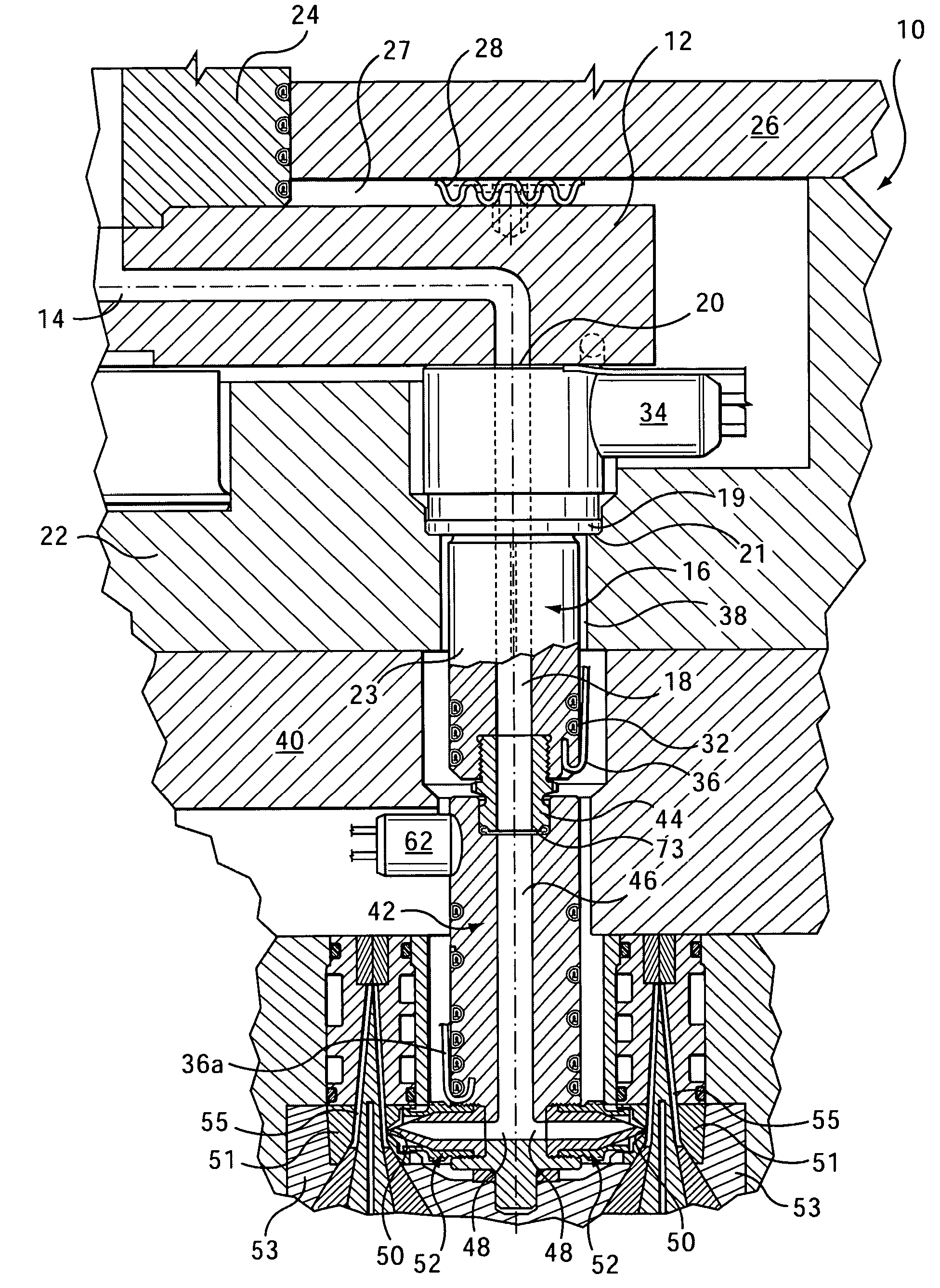
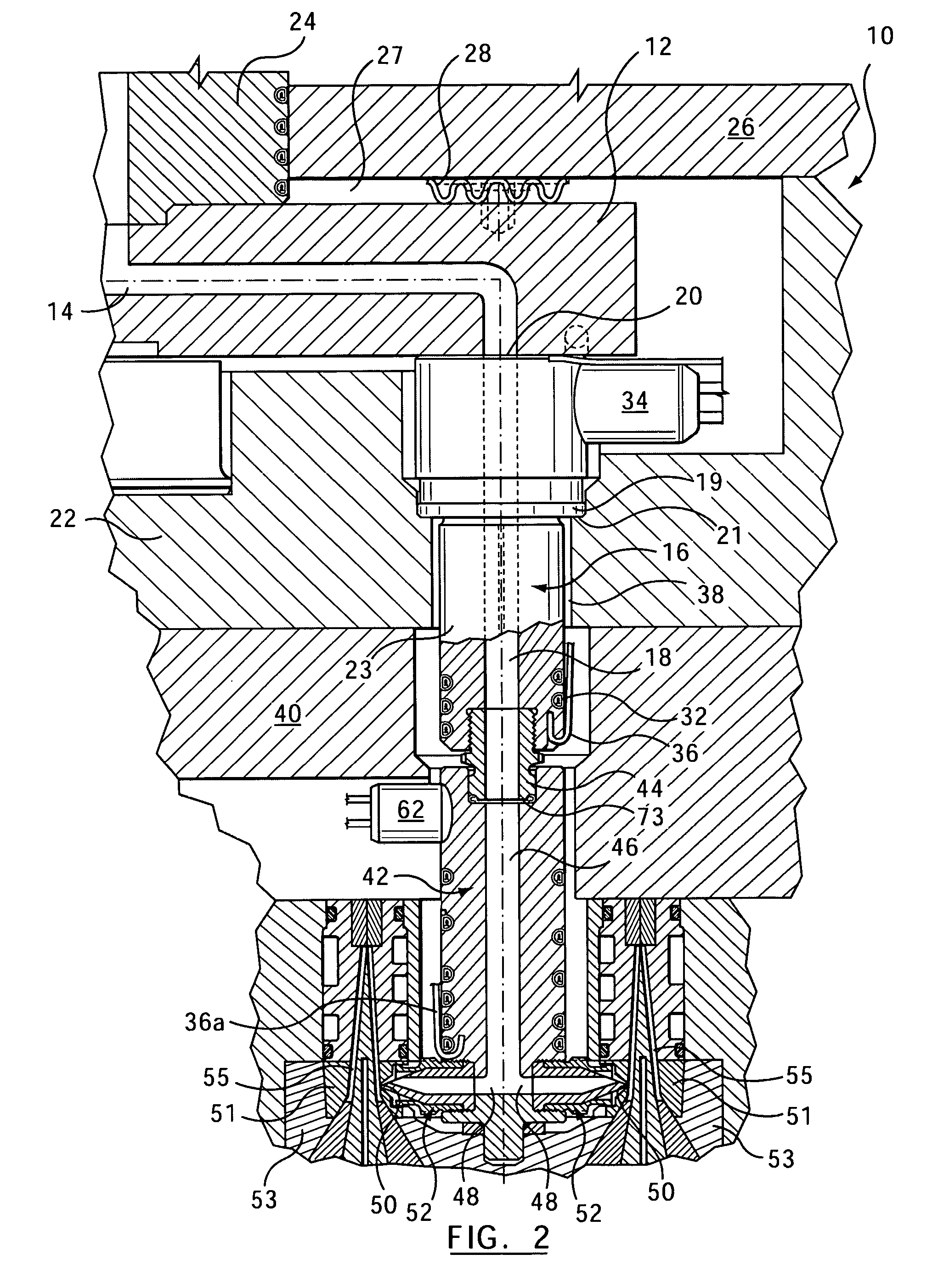
The present invention provides an injection molding apparatus that isolates horizontal gate seals of an edge-gated nozzle from a manifold load by using a dual nozzle arrangement between a mold cavity and the manifold. This allows the edge-gated nozzle to compensate for misalignment caused by heat expansion during operation. The apparatus includes a telescoping linking piece that accommodates the load from the manifold and allows the load from the manifold to be used as sealing means / force between the nozzle and the manifold. The apparatus also includes a heater wrapped about the nozzle for better thermal control and a puck-shaped or brick-shaped nozzle that accommodates more mold gates in a smaller area, increasing production.

Problems solved by technology

Due to the strenuous and repetitive nature of the injection molding process, such a load condition may cause misalignment of the gate seals with their respective mold gates and excessive wear of the gate seals resulting in leakage and more frequent repair and maintenance.

Method used


Image

  • Front-mountable injection molding nozzle
  • Front-mountable injection molding nozzle
  • Front-mountable injection molding nozzle

Examples


Embodiment Construction

[0032]The present invention is intended to be used in an injection molding environment as shown in FIG. 6, which is a partial cross-sectional view of an injection molding system 600. A manifold melt channel 602 extends through a hot runner manifold 604 and is in fluid communication with a melt source from a machine nozzle (not shown) via a sprue bushing 606. A nozzle 610 is positioned within a nozzle cutout 608 of a cavity plate 609. A nozzle melt channel 612 of nozzle 610 is in fluid communication with manifold melt channel 602 for receiving a melt therefrom. Particularly, the melt passes from manifold melt channel 602 through a manifold outlet 603 into nozzle melt channel 612. Nozzle melt channel 612 carries the melt through a nozzle tip 613 towards a mold gate 614 that leads to a mold cavity 616. Injection molding apparatus 600 includes heaters 615 positioned about nozzle 610 and cooling channels 617 in mold-plate 609.

[0033]An edge-gated injection molding apparatus in accordance ...


PUM

PropertyMeasurementUnit
pressureaaaaaaaaaa
lengthaaaaaaaaaa
widthaaaaaaaaaa

Abstract

An injection molding apparatus includes a first, rear-mounted nozzle that is coupled to a manifold for receiving a melt stream therefrom. A second, front-mounted nozzle is coupled to the first nozzle by a nozzle link that is provided between the first and second nozzles. A plurality of gate seals are coupled to a forward end of the second nozzle. The gate seals receive melt from a plurality of melt passages and deliver the melt to a plurality of mold cavities through respective gates. The second nozzle is slidably removable from the first nozzle via the nozzle link to facilitate repair or replacement of the gate seals.

Description

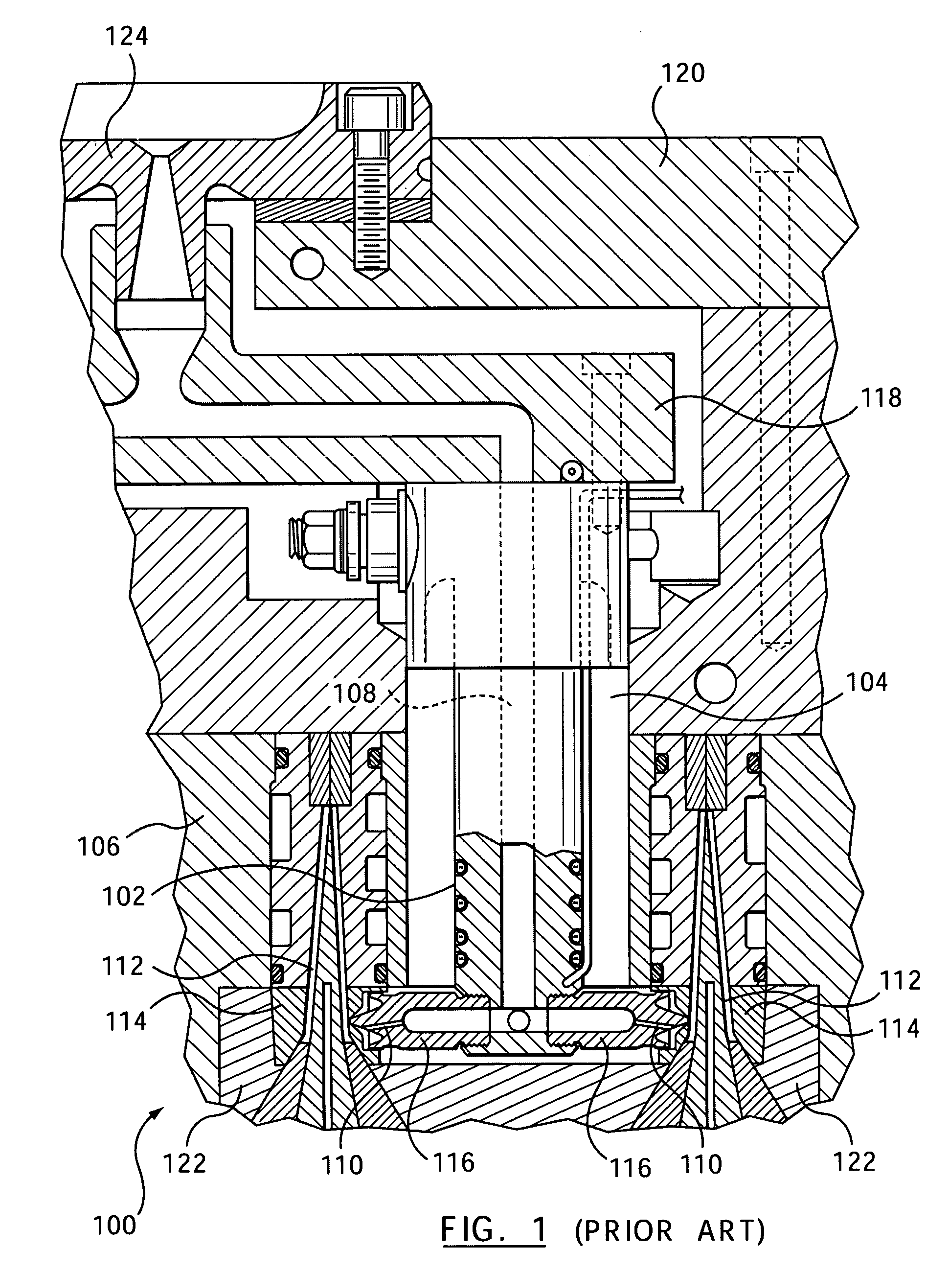
CROSS-REFERENCE TO RELATED APPLICATION[0001]This application is a continuation-in-part of U.S. application Ser. No. 10 / 968,459, filed Oct. 20, 2004, now U.S. Pat. No. 7,179,081 and also which is a continuation-in-part of U.S. application Ser. No. 10 / 819,165, filed Apr. 7, 2004, that claims the benefit under 35 U.S.C. § 119(e) of provisional U.S. Appl. No. 60 / 460,418 filed Apr. 7, 2003, the contents of which are incorporated by reference herein in their entirety.BACKGROUND OF THE INVENTION[0002]1. Field of the Invention[0003]The present invention relates generally to an injection molding apparatus and, in particular, to a front mountable nozzle that delivers melt to a number of mold cavities spaced around the nozzle.[0004]2. Related Art[0005]Edge gating from a nozzle of an injection molding apparatus through a number of edge gate seals is well known. A multi-cavity edge, or side, gated injection molding apparatus 100 is shown in FIG. 1 as described in U.S. Pat. No. 5,494,433 to Gelle...

Claims


Application Information

Patent Timeline
Patent Type & Authority Patents(United States)
IPC IPC(8): B29C45/20B29C45/27
CPCB29C45/27B29C45/2735B29C2045/2798B29C2045/2775B29C2045/2754
Inventor BABIN, DENISSCHWENK, TERRYSICILIA, ROBERT
Owner MOLD MASTERS 2007
Learn More