Holder and communication apparatus

a technology for communication devices and holders, applied in electrical devices, substation equipment, telephone set constructions, etc., can solve the problems lever pieces may be damaged, holder may come off the housing, etc., and achieve the effect of facilitating the attachment operation of the holder with respect to the casing of the communication apparatus and low probability of holder falling o

Inactive Publication Date: 2007-12-11
BROTHER KOGYO KK
View PDF8 Cites 2 Cited by
  • Summary
  • Abstract
  • Description
  • Claims
  • Application Information

AI Technical Summary

Benefits of technology

[0011]The present invention provides a holder which can be detachably attached to a main body of a communication apparatus easily but securely and which is less likely to be damaged even when left detached from the main body. The present invention also provides a communication apparatus having such a holder.
[0014]According to the above-described structure, the second distance by which the engagement portion projects from the first side surface is longer than the first distance by which the lever projects from the first side surface. When the user positions the holder to engage the engagement portion with the casing of the communication apparatus, the lever of the holder is properly positioned so as to correspond to the detection unit disposed on the side of the communication apparatus. Therefore, the attachment operation of the holder with respect to the casing of the communication apparatus is facilitated.
[0015]Also, since the second distance by which the engagement portion projects from the first side surface is longer than the first distance by which the lever projects from the first side surface, even if the holder is left detached from the casing, the probability that the holder is damaged is very low.

Problems solved by technology

In the facsimile machine disclosed in Japanese Patent No. 3,039,602, the attachment operation of the holder is cumbersome because the lever piece that extends from the holder into the housing is needed to be treated carefully.
This results in a problem that the lever piece may be damaged if a strong external force or the like is erroneously caused to act on the holder.
This results in a problem that if the holder is not fixed to the housing with a screw or the like, the holder may come off the housing when the user touches the tongue piece erroneously.

Method used


Image

  • Holder and communication apparatus
  • Holder and communication apparatus
  • Holder and communication apparatus

Examples


Embodiment Construction

[0025]An embodiment of the present invention will be hereinafter described with reference to FIGS. 1-8.

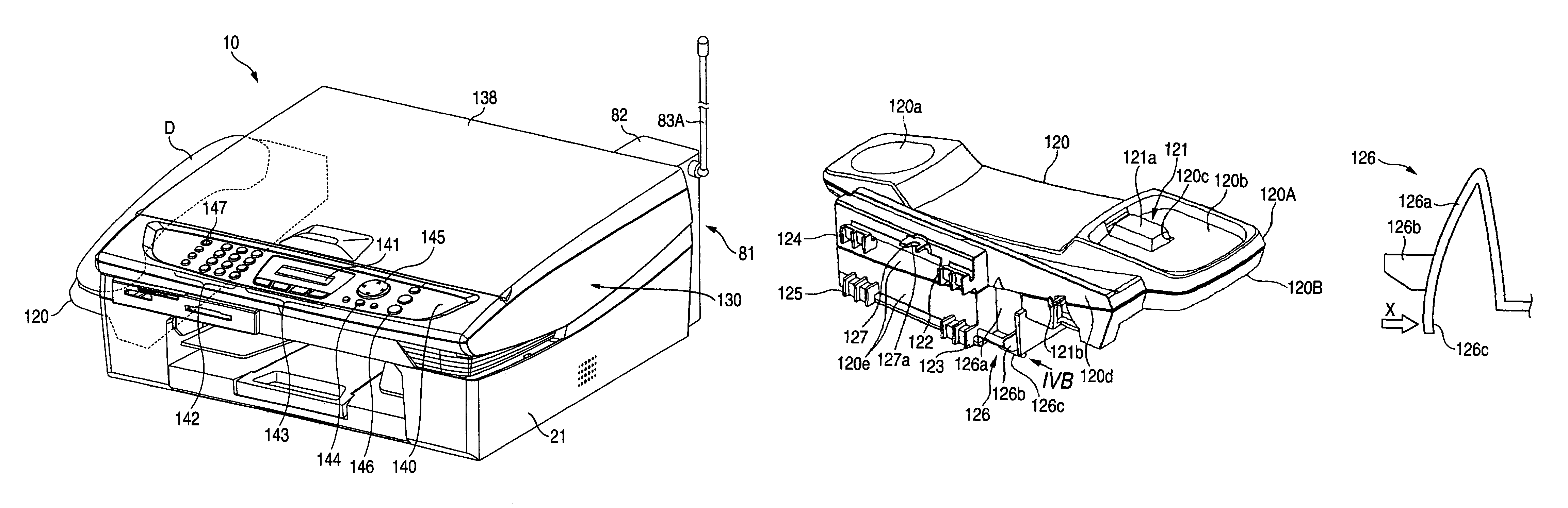
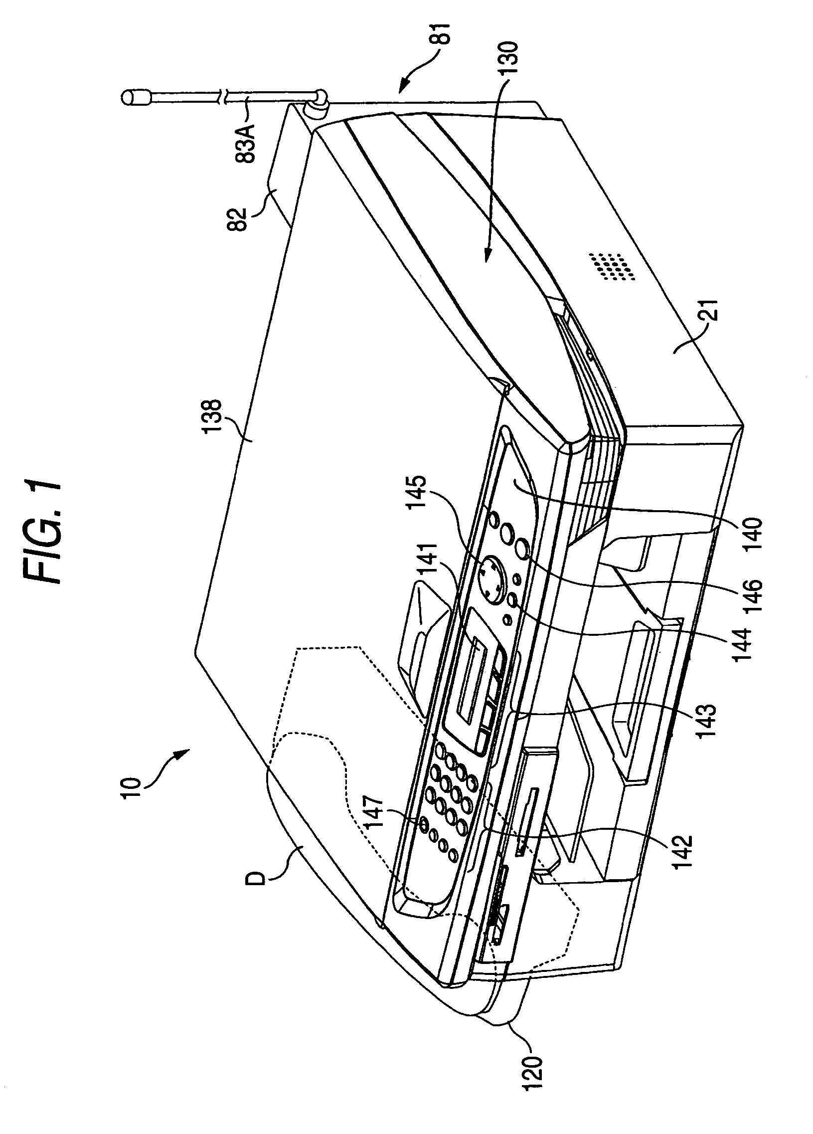
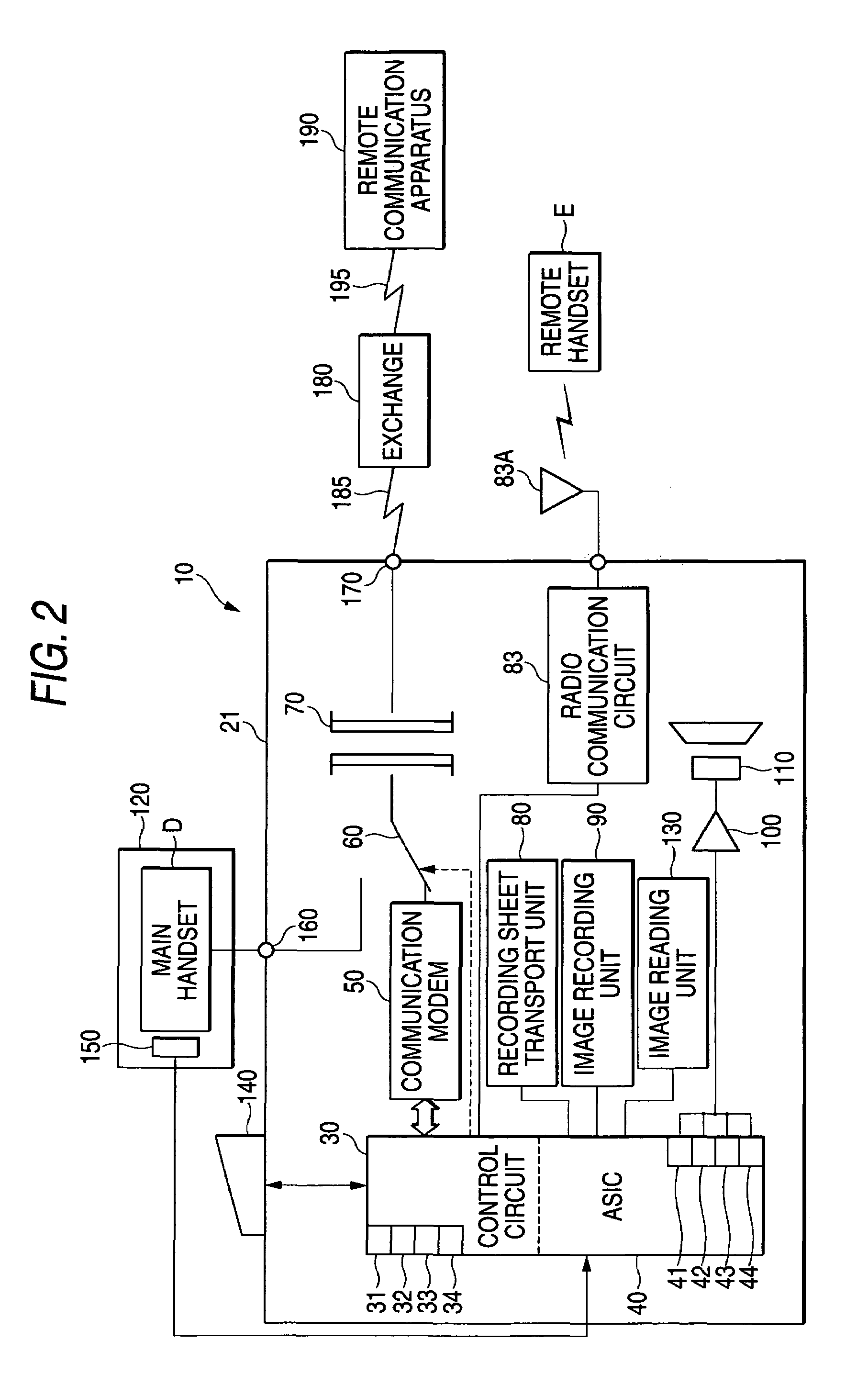
[0026]FIG. 1 is a perspective view of a multifunction machine (which functions as a communication apparatus) 10 according to the embodiment. The multifunction machine 10 has a telephone function, a facsimile function, and a copier function as well as a scanner function and a printer function that are performed when the machine is connected to a personal computer or the like.

[0027]The multifunction machine 10 is configured in such a manner that a flatbed scanner (hereinafter referred to as “image reading unit”) 130 is disposed on top of a machine casing 21 that houses a printer including a recording sheet transport unit 80 and an image recording unit 90 (see FIG. 2). An operating panel 140 that is equipped with various manipulation keys and a display unit (hereinafter referred to as “LCD” (liquid crystal display) 141 is disposed on the front side of the image reading unit 130. The v...


PUM


Abstract

A holder that is detachably attachable to a casing of a communication apparatus, including: a placement surface on which a handset can be placed; a first side surface; a displacement unit that is displaced in response to an act of placing the handset on the placement surface; a lever that is displaced according to a displacement of the displacement unit, the lever being projected in a first direction by a first distance from the first side surface; and an engagement portion being projected substantially in the first direction by a second distance, which is longer than the first distance, from the first side surface, the engagement portion engaging the holder with the casing.

Description

BACKGROUND OF THE INVENTION[0001]1. Field of the Invention[0002]The present invention relates to a holder on which a handset can be placed and which can be attached to and detached from a main body of a communication apparatus, and relates to the communication apparatus.[0003]2. Description of the Related Art[0004]Conventionally, communication apparatus such as facsimile machines have been developed that are configured so as to enable a holder capable of holding a handset thereon to be attached to and detached from their apparatus main body. For example, in a facsimile machine disclosed in Japanese Patent No. 3,039,602, one side wall of a housing is formed with an opening having a prescribed opening area and a holder on which a handset is placed is attached to the opening in a detachable manner. The detachable holder is a resin molded part that is a combination of a top cover and a bottom cover, and a plunger and a lever piece are accommodated in its inside hollow space. The top cov...

Claims


Application Information

Patent Timeline
Patent Type & Authority Patents(United States)
IPC IPC(8): H04M1/00
CPCH04M1/06H04N1/00538H04N2201/0093
Inventor ISHIDA, KAZUHITOKAWAI, TAKAMITSU
Owner BROTHER KOGYO KK
Why Eureka
Try Eureka