Reduction of hysteresis in a magnetoelastic torque sensor

a magnetoelastic torque and sensor technology, applied in the field of reducing hysteresis in the magnetic field of the magnetoelastic torque sensor, can solve the problem that the magnetic field does not return to the desired circumferential orientation

Active Publication Date: 2007-12-18
CONTINENTAL AUTOMOTIVE SYST INC
View PDF14 Cites 26 Cited by
  • Summary
  • Abstract
  • Description
  • Claims
  • Application Information

AI Technical Summary

Benefits of technology

[0009]Accordingly, the method and device according to this device utilizes hysteretic effects imparted into the magnetoelastic material to accommodate and counter undesirable hysteresis imparted within the torque transducer due to the application of torque.

Problems solved by technology

Disadvantageously, in some instances the magnetic field does not return to the desired circumferential orientation once torque is released.

Method used


Image

  • Reduction of hysteresis in a magnetoelastic torque sensor
  • Reduction of hysteresis in a magnetoelastic torque sensor
  • Reduction of hysteresis in a magnetoelastic torque sensor

Examples


Embodiment Construction

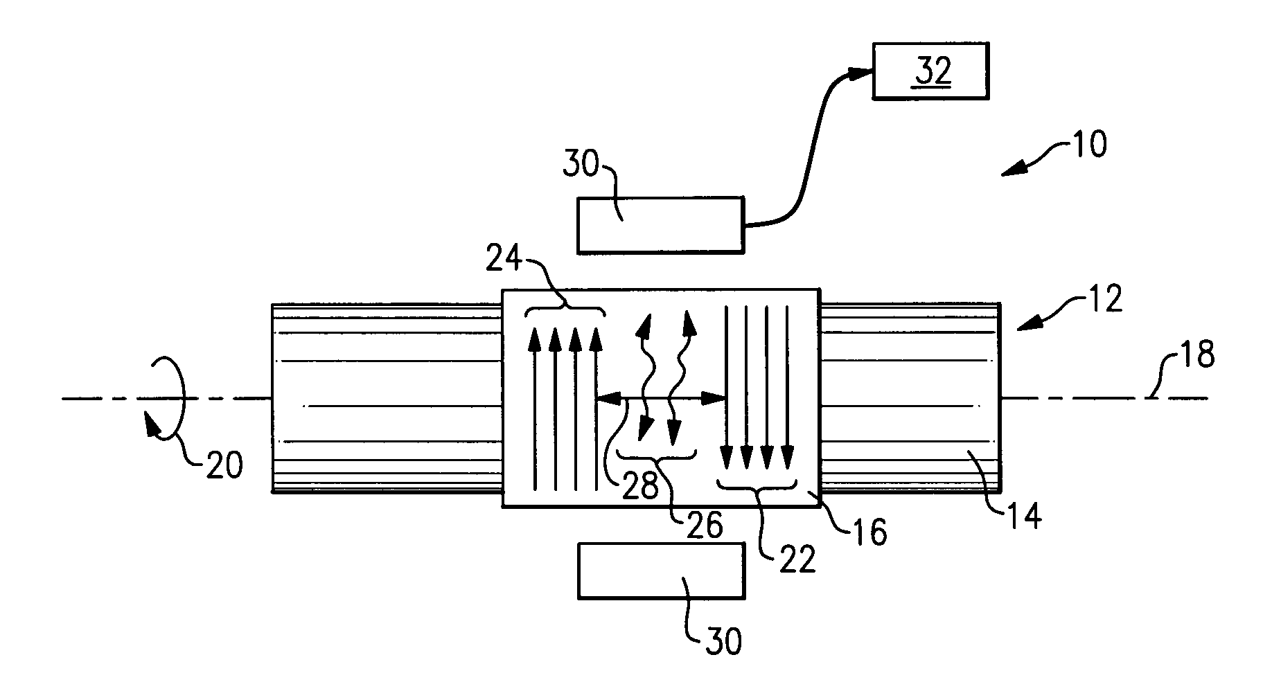
[0016]Referring to FIG. 1, a torque sensor assembly 10 is schematically shown and includes a torque transducer 12 comprising a shaft 14 supporting a magnetoelastic ring 16. The shaft 14 includes an axis 18 and is adapted to receive an applied torque schematically indicated at 20. The torque transducer 12 includes the magnetoelastic ring 16. Within the magnetoelastic ring 16 are preferentially orientated remnant magnetic fields. These preferentially remanent magnetic fields are disposed in a circumferential orientation. During the application of torque, the preferential circumferential magnetic fields are distorted in a helical direction and become imparted with an axial magnetic component.

[0017]The axial magnetic component imparted on the torque transducer 12 is measured by magnetic field vector sensors 30. The magnitude and direction of the axial component of the magnetic fields are measured and provided to a controller 32. The controller 32 translates the vector quantities of the ...


PUM

PropertyMeasurementUnit
circumferential magnetic fieldaaaaaaaaaa
magnetoelasticaaaaaaaaaa
magnetic fieldaaaaaaaaaa

Abstract

A torque sensor assembly includes a reduced hysteresis by imparting a magnetoelastic ring with a first remnant magnetic field and a second remnant magnetic field that are disposed in opposite orientations. The first and second magnetic fields are spaced apart such that a third magnetic field is created within the magnetoelastic ring. The third magnetic field is a loosely pinned magnetic domain that imparts a negative hysteresis within the magnetoelastic ring. The negative hysteresis imparted to the magnetoelastic ring provides for the countering of positive hysteresis created by the application of torque.

Description

BACKGROUND OF THE INVENTION[0001]This invention is generally related to a method and device for fabricating a magnetoelastic torque sensor. More particularly, this invention is related to a method and device for reducing magnetic hysteresis in a magnetoelastic torque sensor.[0002]A magnetoelastic torque sensor utilizes the Inverse-Wiedmann Effect that generates a magnetic field in a magnetoelastic material responsive to the application of torque. A magnetoelastic torque sensor includes a substrate that bears an applied torque and that supports a band of magnetoelastic material. The magnetoelastic band is imparted with a circumferential stress that provides a magnetic easy axis that in turn provides a desired circumferential magnetic field within the magnetoelastic band. Torque on the substrate is transmitted to the band of magnetoelastic material to induce a distortion in the circumferential orientation of the magnetic field. The torque applied to the substrate causes the normally c...

Claims


Application Information

Patent Timeline
Patent Type & Authority Patents(United States)
IPC IPC(8): G01L3/10
CPCG01L3/103G01L3/102
Inventor CRIPE, DAVID W.
Owner CONTINENTAL AUTOMOTIVE SYST INC
Why Eureka
Try Eureka