Electric power connection part of electromagnetic clutch field coil assembly

a technology of electromagnetic clutch field and electric power connection, which is applied in the direction of coupling device connection, magnetic body, magnet, etc., can solve the problems of reducing productivity, diode performance, and increasing costs, so as to reduce manufacturing costs and enhance productivity

Active Publication Date: 2010-08-10
HANON SYST
View PDF33 Cites 11 Cited by
  • Summary
  • Abstract
  • Description
  • Claims
  • Application Information

AI Technical Summary

Benefits of technology

[0015]It is an object of the present invention to provide an electric power connection part of an electromagnetic clutch field coil assembly, which can reduce manufacturing costs and enhance productivity.
[0016]It is another object of the present invention to provide an electric power connection part of an electromagnetic clutch field coil assembly, wherein heat radiated from a field coil assembly and a compressor is not directly transmitted so that damage of an electronic / electric component can be prevented.
[0017]It is a further object of the present invention to provide an electric power connection part of an electromagnetic clutch field coil assembly, wherein a connecting position of a discharge device is controlled so that the discharge can be prevented form being damaged by means of a vibration generated from a vehicle and a compressor.

Problems solved by technology

Thus, a manufacturing process may be added due to the addition of the expoxy treatment process, and a rise in costs and a lowering of productivity are caused due to labor cost.
Accordingly, heat generated from the field coil assembly (1) and the compressor (2) is transmitted directly to the sleeve assembly (11) so that it has a bad influence that performance of the diode (14) and the resistor (15) attached to the sleeve assembly (11) is deteriorated, and the like.
However, since, the housing assembly (12) generally has a configuration in which an additional housing (12-1), a clip (12-2) and a bracket (12-3) are assembled together, a manufacturing process is complicated, they may be deviated from one another in use, and it causes a failure that a wire or the like is adhered to the compressor (2) with a high temperature in deviation.

Method used


Image

  • Electric power connection part of electromagnetic clutch field coil assembly
  • Electric power connection part of electromagnetic clutch field coil assembly
  • Electric power connection part of electromagnetic clutch field coil assembly

Examples


Embodiment Construction

[0030]Hereinafter, preferred embodiments of the present invention will be described in detail with reference to the accompanying drawings.

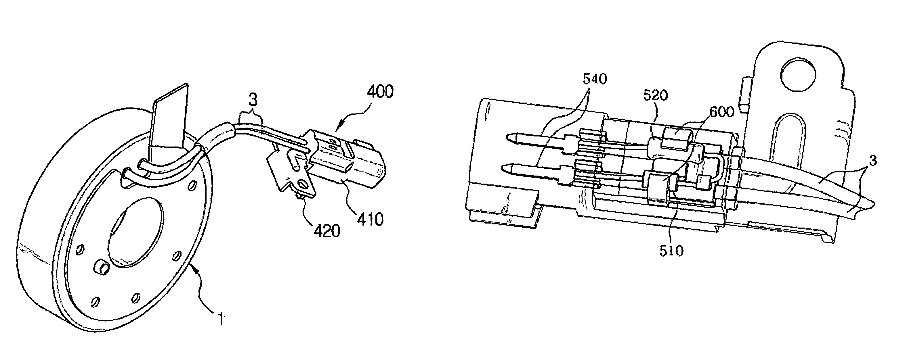
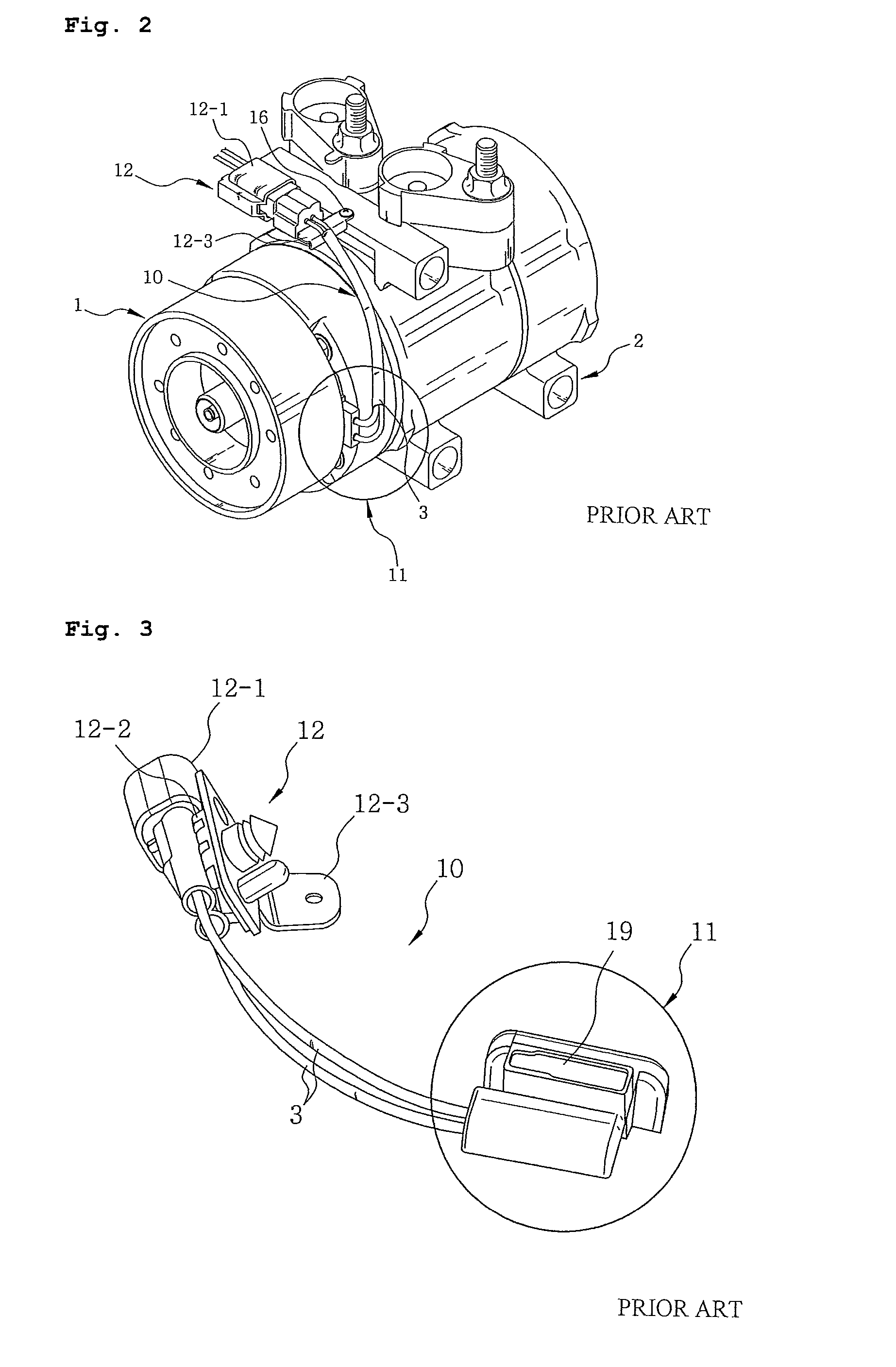
[0031]FIGS. 5, 6a and 6b illustrate structures showing a connection part of an electromagnetic clutch field coil assembly for a vehicle compressor according to this embodiment. In these figures, an electromagnetic clutch field coil assembly(1), a compressor (2) and electric wires (3) refer to a general structure shown in FIG. 2, and the field coil assembly (1) has a configuration in which an electromagnetic coil body (not shown) formed such that an electromagnetic coil is wound in a ring shape inside the field coil assembly (1) is inserted into a coil housing (not shown) while being housed in a bobbin (not shown), and a pair of the electric wires (3) is extracted to the outside.

[0032]As shown in these figures, the electric power connection part of an electromagnetic clutch field coil assembly coupled with a vehicle compressor according to this emb...


PUM

PropertyMeasurementUnit
surge voltageaaaaaaaaaa
magnetic fieldaaaaaaaaaa
coupling structureaaaaaaaaaa

Abstract

An electric power connection part of an electromagnetic clutch field coil assembly connected with an electric power connector at a side of a vehicle engine, includes a housing assembly connected to the field coil assembly with electric wires, which is extracted therefrom, interposed therebetween; a discharge device for absorbing a surge voltage; and a magnetic field elimination device for eliminating a residual magnetic field are injection molded and combonined within the housing assembly. Accordingly, the electric power connection part has an advantage in that it is not directly influenced by heat radiated from a field coil assembly so that electric / electronic devices can be prevented from being damaged; since an epoxy applying process for attaching electric / electronic devices such as a discharge device and a magnetic field elimination device is omitted, a manufacturing process is greatly simplified; and the number of components are reduced so that manufacturing process thereby decreasing costs.

Description

TECHNICAL FIELD[0001]The present invention relates to an electric power connection part of an electromagnetic clutch field coil assembly coupled with a vehicle compressor, and more particularly, to a structure of an electric power connection part of an electromagnetic clutch field coil assembly, which can reduce operation processes and costs, and normally maintain performance of a component for a long period of time.BACKGROUND ART[0002]In general, a vehicle compressor for an air conditioner is operated by means of a driving force of an engine, and an electromagnetic clutch is mounted together to intermittently operate only in a case where air conditioning is required.[0003]FIG. 1 illustrates a general coupling structure of a vehicle compressor and an electromagnetic clutch. An operation principle of the compressor (2) will be briefly described below with reference to FIG. 1.[0004]First, in a case where an engine is operating, a pulley (6) connected from a driving shaft of the engine...

Claims


Application Information

Patent Timeline
Patent Type & Authority Patents(United States)
IPC IPC(8): H01F7/00H01F1/00
CPCH01R13/6666H02K5/225H01F17/06H01F27/402H01F2007/062H01R43/00
Inventor OH, SUNG TAEGCHO, SUNG WONPARK, DAE YONGSHIN, HWA YOUPSONG, JUN-HOLIM, UK GYU
Owner HANON SYST
Why Eureka
Try Eureka