Magnetic immunoassay system

a magnetic immunoassay and immunoassay technology, applied in the field of magnetic immunoassay systems, can solve the problems of increasing the minimum detection limit, reducing the signal-to-noise ratio, and unable to completely reduce the magnetic field to zero, so as to achieve high immunoassay sensitivity, eliminate the effect of magnetic signals, and easy isolating signals

Inactive Publication Date: 2007-11-01
HITACHI LTD
View PDF6 Cites 9 Cited by
  • Summary
  • Abstract
  • Description
  • Claims
  • Application Information

AI Technical Summary

Benefits of technology

[0020] Performing immunoassay analysis possessing the advantage that remanence or magnetic relaxation is measured without a washing (B / F separation) process, requires that the direction of magnetic monemtum of each unbound magnetic marker within the solution be random by Brownian motion. The magnetic signals from the unbound magnetic marker 7c in this case cancel each other out so that no magnetic signals are detected from the solution (FIG. 1E). However, results from experiments conducted by the present inventors revealed that unbound magnetic markers emit magnetic signals from within the solution due to the unbound magnetic markers being aligned in the direction of a residual magnetic field within the magnetic shield section. The residual (magnetic) field within the periphery of the sensor and the sample could be reduced by magnetic shielding but completely reducing this magnetic field to zero was impossible.
[0023] Whereupon, an object of the present invention is to provide a method capable of easily eliminating the effects of residual magnetic fields that cannot be reduced by magnetic shields, and also to provide a high-sensitivity magnetic immunoassay system capable of sufficiently reducing the effect of signals from unbound markers.
[0031] Therefore if the captured magnetic marker to be measured is magnetized in the x or the z direction, and the magnetization direction of the unbound magnetic marker in the solution causing the noise is controlled to intersect the magnetization direction of the bound magnetic marker, then the waveforms that are obtained will be two waveforms with different symmetry, or in other words, the sum of the captured marker waveform and the waveform of the marker within the solution. The waveform of the captured marker can be easily obtained by utilizing the difference in symmetry between these measured waveforms.
[0033] In FIG. 4, a SQUID gradiometer containing a first order planar gradiometric pickup coil is utilized instead of a SQUID magnetometer. FIG. 4 shows the signal waveforms detected in the SQUID when a magnetic sample has passed over it. The x-z planar surface is omitted in FIG. 4. The coil surface of the gradiometric pickup coil is also arrayed along the x-y planar surface in FIG. 4, and the magnetic sample passes along the x direction, directly beneath the pickup coil parallel with the x-y planar surface. The direction perpendicular to the pickup coil is z, the sample direction of movement is x, and here y is a direction perpendicular to x and z. The (a), (b), and (c) in FIG. 4 show the case where are each the same as (a), (b), and (c) in FIG. 3, and the case is shown where the magnetic sample is magnetized in the x, y, and z directions. The differential direction of the gradiometric pickup coil is the x direction, and the solid line and the dotted line of the pickup coil in the drawing show that the pickup coil polarity is reversed. Unlike FIG. 3, the signal waveforms detected in the SQUID when the magnetic sample is magnetized in the x direction, y direction and the z direction are bilaterally symmetrical, zero and are central symmetrical. Just as with the magnetometer shown in FIG. 3, the signal waveforms detected in the SQUID from the sample magnetized in the z direction, and the sample magnetized in the x direction possess different symmetry so that the signals can be easily isolated. The magnetic signals from the sample magnetized in the y direction, as expected, cannot be detected so there is no need to isolate the signals.
[0036] Reducing the direct current field to zero in all directions with a magnetic shield is impossible but the magnetic field in one direction can easily be controlled, as used in this invention. A compensation coil can be installed for example in the vicinity of the SQUID magnetic sensor and the residual magnetic field components in the vicinity of the measurement position canceled in one direction out by adjusting the direct current flowing to the compensation coil. Moreover, controlling the magnetization direction of unbound magnetic markers in the solution to a direction perpendicular to the magnetization direction of bound magnetic markers is comparatively simple. A permanent magnet or a coil for example can be installed to control the magnetization direction of unbound magnetic markers in the solution by applying a magnetic field. Controlling the direction of the residual magnetic field within the shield is also comparatively simple. In the case of a cylindrical magnetic shield for example, the shield rate along the center axis of the tube is lower than a direction perpendicular to the center axis so that a magnetic field can be left remaining along the center axis in the center of the cylindrical magnetic shield.
[0038] This invention is capable of easily isolating signals from bound magnetic markers even when magnetic signals are emitted from magnetic markers in a liquid state due to a residual magnetic field. The present invention can therefore eliminate the effects from magnetic signals emitted by magnetic markers in a liquid state and provide a high sensitivity immunoassay. Moreover this invention does not require a magnetic shield with good multilayer sealing that was required for high sensitivity immunoassays so this invention can reduce equipment costs and improve operability.

Problems solved by technology

The residual (magnetic) field within the periphery of the sensor and the sample could be reduced by magnetic shielding but completely reducing this magnetic field to zero was impossible.
The magnetic signals from these unbound magnetic markers become background signals (noise) causing a drop in the signal-to-noise (SN) ratio and an increase in the minimum detection limit when attempting to measure a fixed magnetic marker.

Method used


Image

  • Magnetic immunoassay system
  • Magnetic immunoassay system
  • Magnetic immunoassay system

Examples


first embodiment

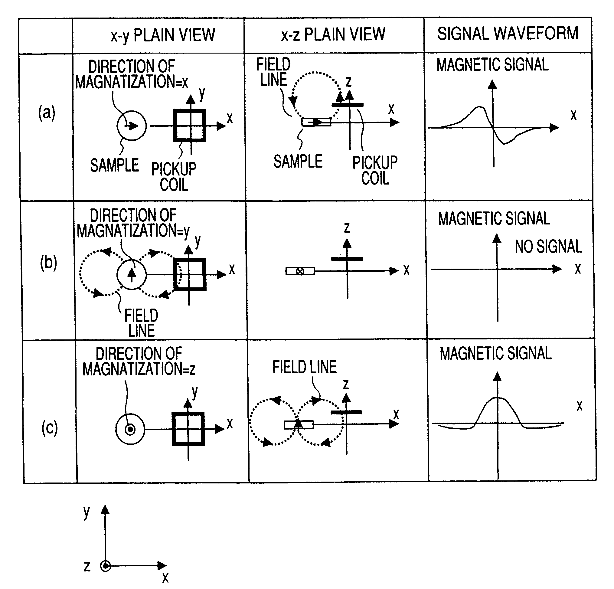
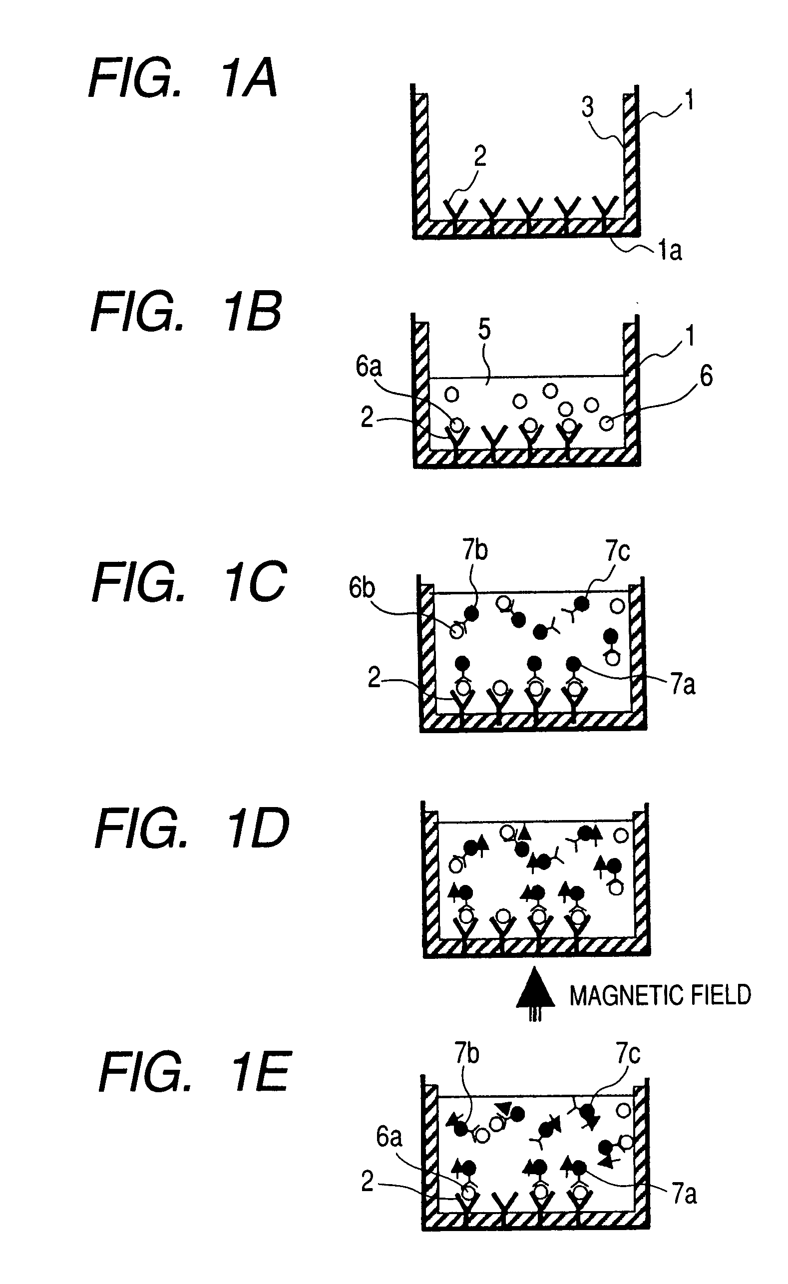
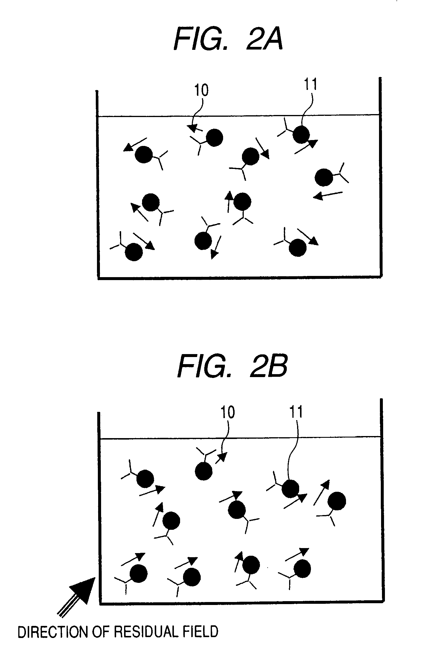
[0059] The following description utilizes antibodies labeled with magnetic nanoparticles (magnetic markers) containing residual magnetic signals, and the description of the embodiment of this invention utilizes a magnetic immunoassay system for detecting magnetic signals from a sample reacting with a test reagent in a first-order planar SQUID gradiometer as an example. The following disclosure is nothing more than an embodiment of this invention, and does not limit the technical scope of this invention.

[0060]FIG. 5 is a cross sectional view showing the structure of the first-order gradiometer SQUID of the first embodiment of this invention. In order to reduce the input of magnetic environmental noise into the SQUID, the cooler device (made up of an outer tank 21, a vacuum layer for thermal insulation 22 and inner tank 23) for cooling the SQUID is enclosed by an RF shield 19 and magnetic shields 30, 31. The RF shield 19 is made from metal material with low electrical resistance such...

second embodiment

[0075] An example of the second embodiment is described utilizing a magnetic immunoassay system for detecting magnetic signals from a sample that reacted with a test reagent in a first-order planar SQUID gradiometer, using antibodies labeled with magnetic nanoparticles having remanence.

[0076]FIG. 13 is a cross sectional view showing the structure of the magnetic immunoassay system of the second embodiment. A permanent magnet 18 and a position adjuster 20 for the permanent magnet are installed instead of the compensation coil 16 for the system used in the first embodiment shown in FIG. 5. The permanent magnet 18 applies a magnetic field in a direction perpendicular to the magnetization direction (z direction) of the bound magnetic marker at the measurement position. The other parts of the structure are identical to the first embodiment.

[0077] A sample identical to that for the first embodiment was measured using this system. The method for making the samples was identical to that o...

third embodiment

[0079] An example of the third embodiment is described utilizing a magnetic immunoassay system for detecting magnetic signals from a sample that reacted with a test reagent in a first-order planar SQUID gradiometer, using antibodies labeled with magnetic nanoparticles having remanence.

[0080]FIG. 15 is a cross sectional view showing the structure of the system. The system utilizes a dual layer cylindrical magnetic shield made from a cylindrical magnetic shield 43 with an inner diameter of 40 centimeters and length of 1 meter, and a cylindrical magnetic shield 44 with an inner diameter of 30 centimeters and length of 90 centimeters. The shield 43 and 44 material is 2 millimeter thick permalloy. A sample container 45 is a non-magnetic reaction chamber with an 8 by 12 array of 96 holes. The sample container 45 is supported by a sample container holder 47 so that the measurement position is at the center of the magnetic shield, and a 3-axis manipulator 48 moves the desired sample to the...


PUM

PropertyMeasurementUnit
magnetic fieldaaaaaaaaaa
electrical currentaaaaaaaaaa

Abstract

A magnetic immunoassay system with a mechanism for compensating the direct current residual magnetic field in the vicinity of the specimen measurement position, in a direction perpendicular to the magnetic marker direction of magnetization for the measurement target. This invention reduces the effects of the magnetic field emitted from the unbound magnetic marker due to the residual magnetic field in the specimen solution and detects with high sensitivity the signal of the bound target magnetic marker. The magnetic field at the measurement position is regulated so as to intersect the direction of magnetization of the magnetic marker for the measurement target, in order to make the magnetization direction of the magnetic marker that is unbound due to residual magnetism or remanence in the sample solution, intersect the magnetization direction of the magnetic marker for the measurement target. The signal of the bound target magnetic marker can be therefore measured with high sensitivity since it is isolated from the unbound magnetic marker signal.

Description

CROSS-REFERENCE TO RELATED APPLICATION [0001] This application is a Divisional application of U.S. application Ser. No. 11 / 699,375 filed Jan. 30, 2007. Priority is claimed based on U.S. application Ser. No. 11 / 699,375 filed Jan. 30, 2007, which claims the priority of Japanese Patent Application No. 2006-063776 filed on Mar. 9, 2006, all of which is incorporated by reference.FIELD OF THE INVENTION [0002] The present invention relates to a system for analyzing different types of protein (immunoglobulin, tumor markers, and hormones, etc.), disease-causing germs, cancer cells, DNA and environmental toxins by utilizing magnetic nanoparticles, and relates in particular to a magnetic immunoassay system utilizing a superconducting quantum interference device (SQUID). BACKGROUND OF THE INVENTION [0003] Demands are increasing in recent years for high sensitivity in the examination of environmental toxins, DNA, cancer cells and disease-causing germs of different types by their immuno-reaction....

Claims


Application Information

Patent Timeline
Patent Type & Authority Applications(United States)
IPC IPC(8): G01N27/00
CPCG01N33/54326
Inventor TSUKAMOTO, AKIRASAITOH, KAZUO
Owner HITACHI LTD
Why Eureka
Try Eureka