Device for applying a ventrally or dorsally directed translatory force in the area of a knee joint

a translation force and dorsal technology, applied in non-surgical orthopedic devices, restraining devices, medical science, etc., can solve the problems of affecting the function of the knee joint, so as to prevent undesired tibial displacement and allow the knee joint to move freely.

Active Publication Date: 2007-12-18
ALBRECHT
View PDF10 Cites 28 Cited by
  • Summary
  • Abstract
  • Description
  • Claims
  • Application Information

AI Technical Summary

Benefits of technology

[0006]Starting out from this, the object of the invention is to make available a device of the type mentioned at the outset which, in a particularly effective way, prevents undesired displacement of the tibia in the dorsal direction or ventral direction and permits free mobility of the knee joint.

Problems solved by technology

In the field of knee instability, posterior cruciate ligament lesions in particular pose considerable medical problems.
Although there are well proven surgical reconstruction procedures for posterior cruciate ligament ruptures and other lesions of the posterior cruciate ligaments, the result of surgery has often deteriorated after a few months, or been lost altogether, because the sutured or reconstructed ligament has been stretched again in an undesired manner on account of the gravitational force of the lower leg which, with the patient lying on his back, acts in the dorsal direction.
This leads to incorrect positioning of the tibia relative to the femur, as is indicated by broken lines in FIG. 1.
The risk of this kind of incorrect positioning, i.e. dropping of the tibia relative to the femur, also arises of course when a posterior cruciate ligament lesion is treated, not surgically, but by conservative methods.
In the case of anterior cruciate ligament instability, a problem which may occur is that the tibia comes to lie too far in the ventral direction relative to the femur.
A problem with this known device, however, is that the spring force on the lower leg means that a permanent force is exerted in the extension direction or flexion direction, i.e. a torque which seeks to permanently extend or flex the lower leg.
A free and unimpeded extension or flexion of the knee is therefore not possible with this known device.

Method used


Image

  • Device for applying a ventrally or dorsally directed translatory force in the area of a knee joint
  • Device for applying a ventrally or dorsally directed translatory force in the area of a knee joint
  • Device for applying a ventrally or dorsally directed translatory force in the area of a knee joint

Examples


second embodiment

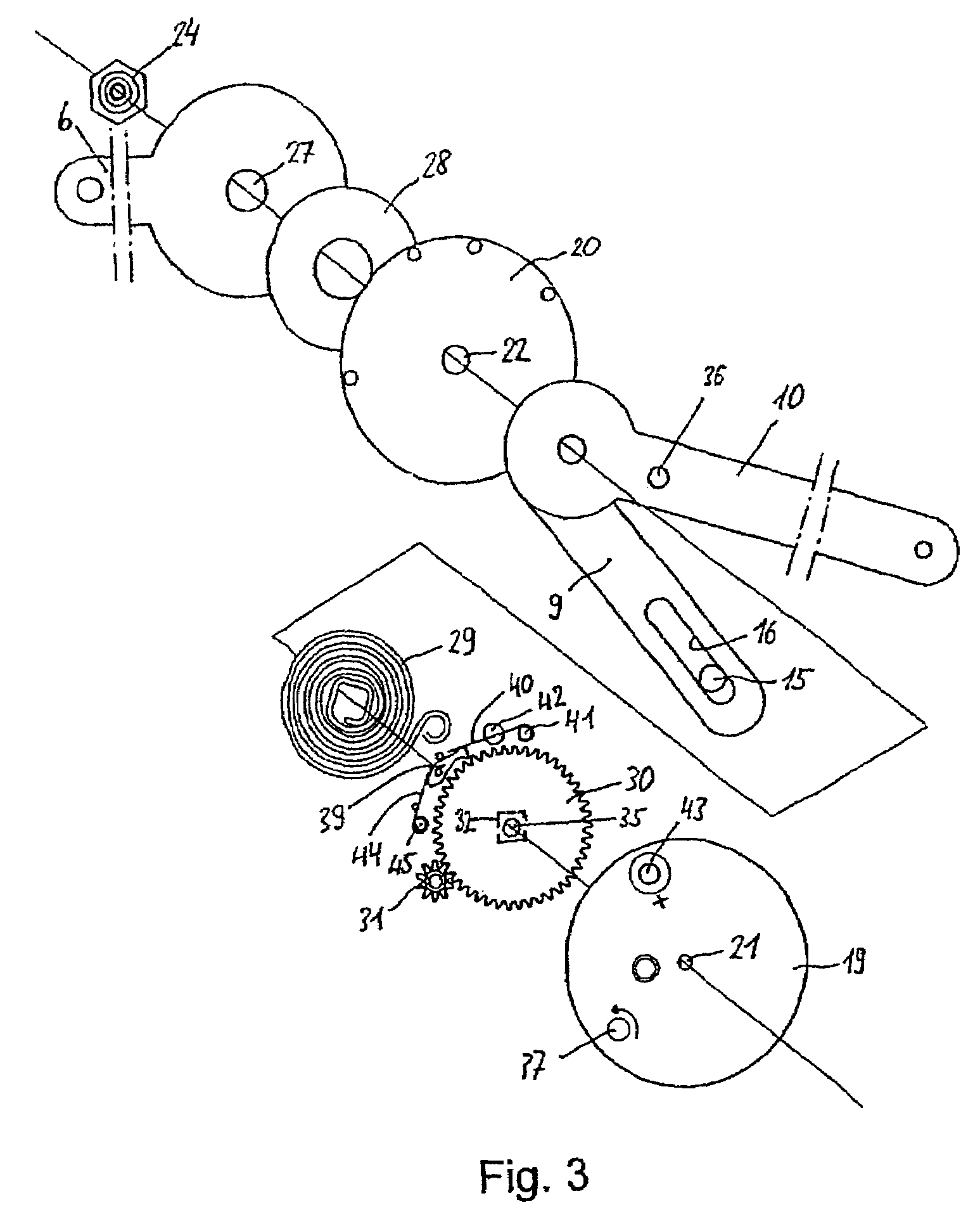
[0050]FIGS. 10 and 11 show the device according to the invention in which the thigh bar 6, in the hinge area, has an oblong hole 46 extending in the longitudinal direction of the thigh bar 6. The thigh bar 6 is shown on its own in FIG. 13. The oblong hole 46 means that the screw 23 serving as swivel axis, and thus the entire lower-leg bar device, can move together with the spring housing 19 by a defined distance along the oblong hole 46.

[0051]The nut 24 used in this embodiment is shown in FIG. 12. Like the nut in the first embodiment, this nut 24 again has a cylindrical collar 26 which engages in the oblong hole 46 and is guided by the long side walls of the oblong hole 46 with slight play. The other parts of the second embodiment are identical to those of the first embodiment and are therefore not described again in detail here.

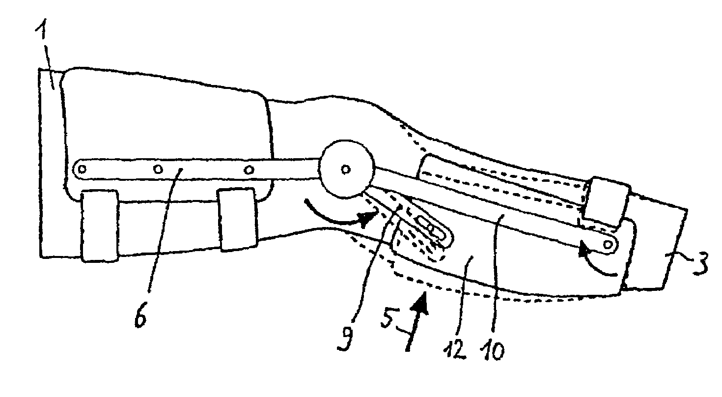
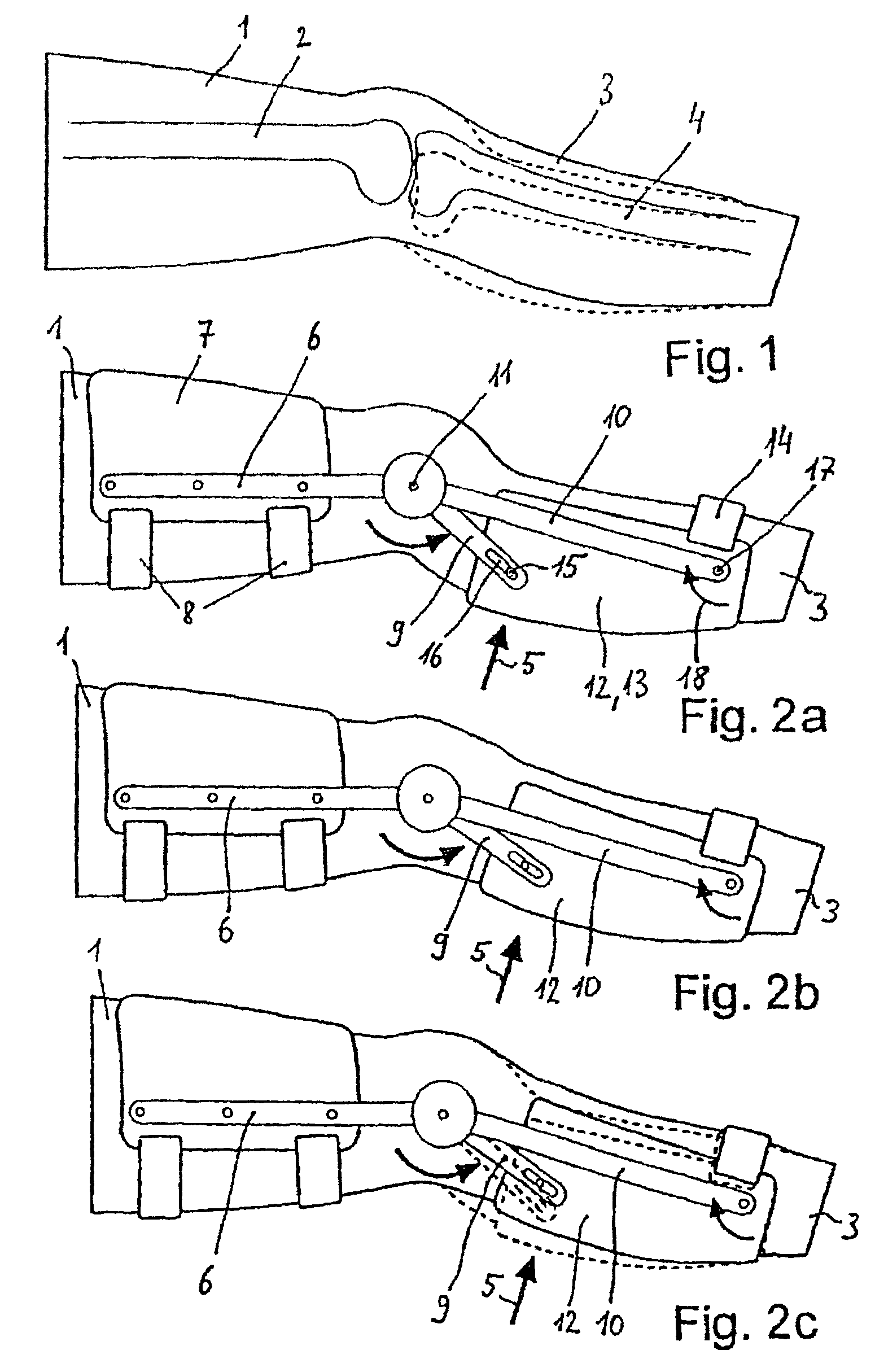
[0052]The way in which the second embodiment works is identical to that of the first embodiment. The shorter bar arm 9 is moved in the arrow direction (see ...

first embodiment

[0053]This causes a reaction force which presses the end area of the lower-leg bar device in the dorsal direction in the hinge area. Since the thigh bar 6, however, is fixed securely on the thigh via the cuff 7, the hinge area of the device is held in a fixed position relative to the knee joint. Upon flexion of the knee joint, however, the force acting in the hinge area seeks to displace the cuff 7 of the thigh slightly in the proximal direction. Upon subsequent extension, by contrast, a tension stress, possibly felt to be unpleasant, would be exerted on the thigh bar 6 if the lower-leg bar device were mounted non-displaceably on the thigh bar, as is the case in the However, the oblong hole 46, which is provided in the thigh bar 6 and is situated laterally and centrally alongside the knee joint, permits a displacement of the bearing along the oblong hole 46, such that tension or compression forces can be avoided in the longitudinal direction of the thigh.


PUM


Abstract

A device for applying a ventrally or dorsally directed translatory force onto a lower leg in the area of the knee joint includes a thigh bar and a lower leg bar device having a shorter and a longer bar arm. Both bar arms can be freely swiveled relative to the thigh bar. The two bar arms are disposed in such a manner that they can be swiveled relative to each other. A pretension of a spring device between the shorter and the longer bar arm has the effect that the bar arms are urged to carry out a swiveling motion relative to each other, thereby applying a ventrally or dorsally directed translatory force onto a lower leg fixation device in an area close to the knee.

Description

[0001]This application is the US national phase of international application PCT / EP2003 / 001456 filed 13 Feb. 2003 which designated the U.S. and claims benefit of DE 102 59751.0, filed 19 Dec. 2002, the entire contents of each of which are hereby incorporated by reference.BACKGROUND OF THE INVENTION[0002]The invention relates to a device for applying a ventrally or dorsally directed translatory force onto a lower leg in the area of a knee joint for treatment or follow-up treatment of knee instability, in particular cruciate ligament instability.[0003]In the field of knee instability, posterior cruciate ligament lesions in particular pose considerable medical problems. Although there are well proven surgical reconstruction procedures for posterior cruciate ligament ruptures and other lesions of the posterior cruciate ligaments, the result of surgery has often deteriorated after a few months, or been lost altogether, because the sutured or reconstructed ligament has been stretched agai...

Claims


Application Information

Patent Timeline
Patent Type & Authority Patents(United States)
IPC IPC(8): A61F5/00A61F5/01
CPCA61F5/0125A61F2005/0179A61F2005/0146
Inventor ALBRECHT, ERICHOPAHLE, HANS-GEORG
Owner ALBRECHT
Why Eureka
Try Eureka