Cooling system for computer systems

Inactive Publication Date: 2007-12-18
HEWLETT-PACKARD ENTERPRISE DEV LP
View PDF6 Cites 151 Cited by
  • Summary
  • Abstract
  • Description
  • Claims
  • Application Information

AI Technical Summary

Problems solved by technology

In recent years, these components have become more dense and, hence, generate more heat during operation.
Excessive heat tends to adversely affect the performance and operating lives of these components.
Furthermore, when a plurality of computer systems are stored in the same location, as in a rack, there is an even greater potential for the adverse effects of overheating.
Operation at temperatures above maximum operating temperatures may result in irreversible damage to the components.
Typically, the distribution of

Method used


Image

  • Cooling system for computer systems
  • Cooling system for computer systems
  • Cooling system for computer systems

Examples


Embodiment Construction

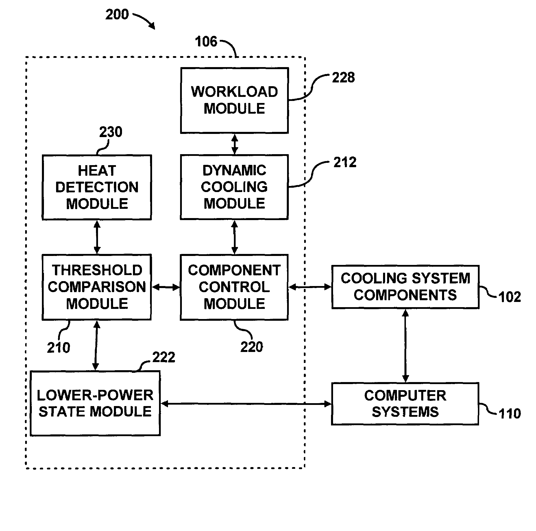
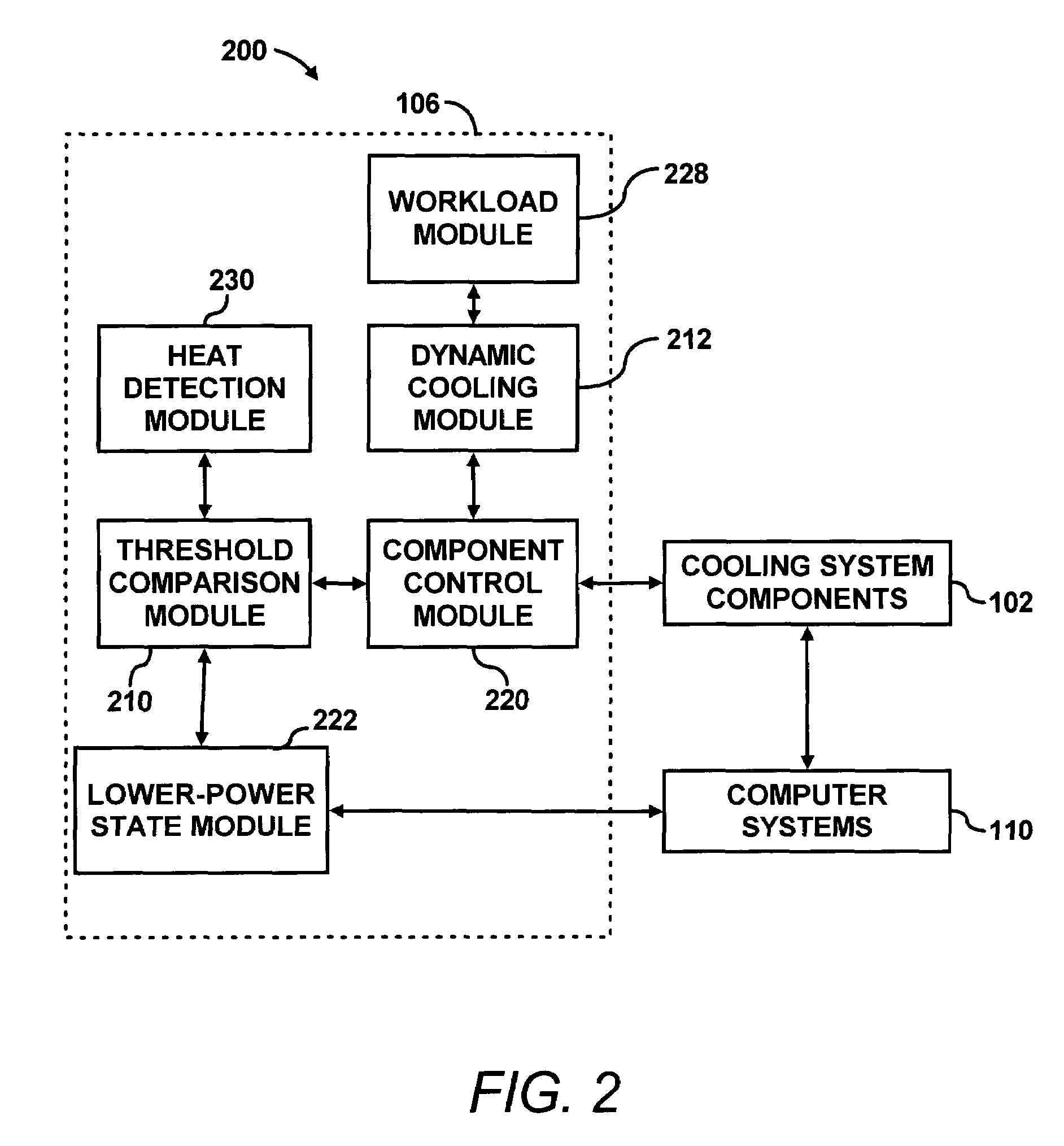
[0024]According to an embodiment, a cooling system for one or more computer systems is designed and implemented based on a nominal heat dissipation of the computer systems (i.e., heat generated by components of the computer systems) rather than being based on maximum heat dissipation by the computer systems. For example, nominal heat dissipation may be estimated based on the average heat dissipated by components of the computer systems, or nominal heat dissipation may be a standard deviation of the average heat dissipation. Other statistical techniques may be used to determine nominal heat dissipation, which may be based on actual measurements or estimations of heat dissipation. Alternatively, the nominal heat dissipation may be based on the heat dissipation of a computer system running a typical workload (e.g., the workload the computer system may run for a majority of its operation time). The workload of a computer system may be known or estimated by historical measurements of wor...


PUM


Abstract

A cooling system for cooling computer systems detects heat dissipated by the computer systems. If the heat dissipated by the computer systems exceeds a threshold, at least one component of the computer systems is placed in a lower-power state to reduce heat dissipation.

Description

FIELD OF THE INVENTION[0001]This invention relates generally to cooling systems. More particularly, the invention relates to cooling systems for computer systems.BACKGROUND OF THE INVENTION[0002]Computer systems typically include components that generate / dissipate considerable amounts of heat. These components may include one or more processors (e.g., central processing units, multi-chip modules, etc.), system boards having printed circuit boards (PCBs) in general, memory, power supplies, and other circuits. In recent years, these components have become more dense and, hence, generate more heat during operation. Excessive heat tends to adversely affect the performance and operating lives of these components. Furthermore, when a plurality of computer systems are stored in the same location, as in a rack, there is an even greater potential for the adverse effects of overheating.[0003]In order to substantially guarantee proper operation, and to extend the life of the computer systems, ...

Claims


Application Information

Patent Timeline
IPC IPC(8): G06F1/26G06F1/16H05K7/20
CPCH05K7/20736G06F1/20
Inventor PATEL, CHANDRAKANT D.FARKAS, KEITH ISTVANJANAKIRAMAN, GOPALAKRISHNAN
Owner HEWLETT-PACKARD ENTERPRISE DEV LP
Why Eureka
Try Eureka