Apparatuses for interaction with a subterranean formation, and methods of use thereof
What is AI technical title?
AI technical title is built by Patsnap AI team. It summarizes the technical point description of the patent document.
a technology of subterranean formation and subterranean water, which is applied in the field of methods and apparatus for interaction with a subterranean formation, can solve the problems of not being able to be installed directly through hardened soil, concrete, steel, other metals or waste products, and not being easily repaired or replaced
Inactive Publication Date: 2007-12-25
BATTELLE ENERGY ALLIANCE LLC
View PDF100 Cites 22 Cited by
Summary
Abstract
Description
Claims
Application Information
AI Technical Summary
This helps you quickly interpret patents by identifying the three key elements:
Problems solved by technology
Method used
Benefits of technology
Problems solved by technology
Water and associated contaminant movement within the vadose zone may influence, to a large degree, a quantity of contamination (such as gasoline additives, agricultural chemicals, or buried waste leakage) that may be distributed in a water supply (such as an aquifer).
Another problem associated with conventional hydrogeological sensors may be fragility.
Often, conventional hydrogeological sensors are made of ceramic, tin, copper, plastics, or similar such materials and cannot be installed directly through difficult materials such as hardened soils, concrete, steel, other metals, or waste products.
Further, even if a conventional hydrogeological sensor is successfully placed within a subterranean region, it may not easily be repaired or replaced.
Also, placing conventional probes into a contaminated subterranean formation for data collection may not be desirable, because the placing of conventional probes may often require drilling or coring which would bring contaminated “cuttings” to the surface and may also allow contaminated emissions to escape from the hole which is drilled.
Unfortunately, such probe placement only provides information when a contaminant has migrated outside of the waste disposal site area.
As a further disadvantage, when a contaminant has migrated outside of the waste disposal site area, it is likely that a major contaminant plume may already exist, thus making potential remediation and containment efforts more difficult and costly.
However, the function of the apparatus disclosed by U.S. Pat. No. 6,826,972 to Clark is limited to a lysimeter.
Method used
Image
Click on the blue label to locate the original text in one second.
Reading with bidirectional positioning of images and text.
Examples
Embodiment Construction
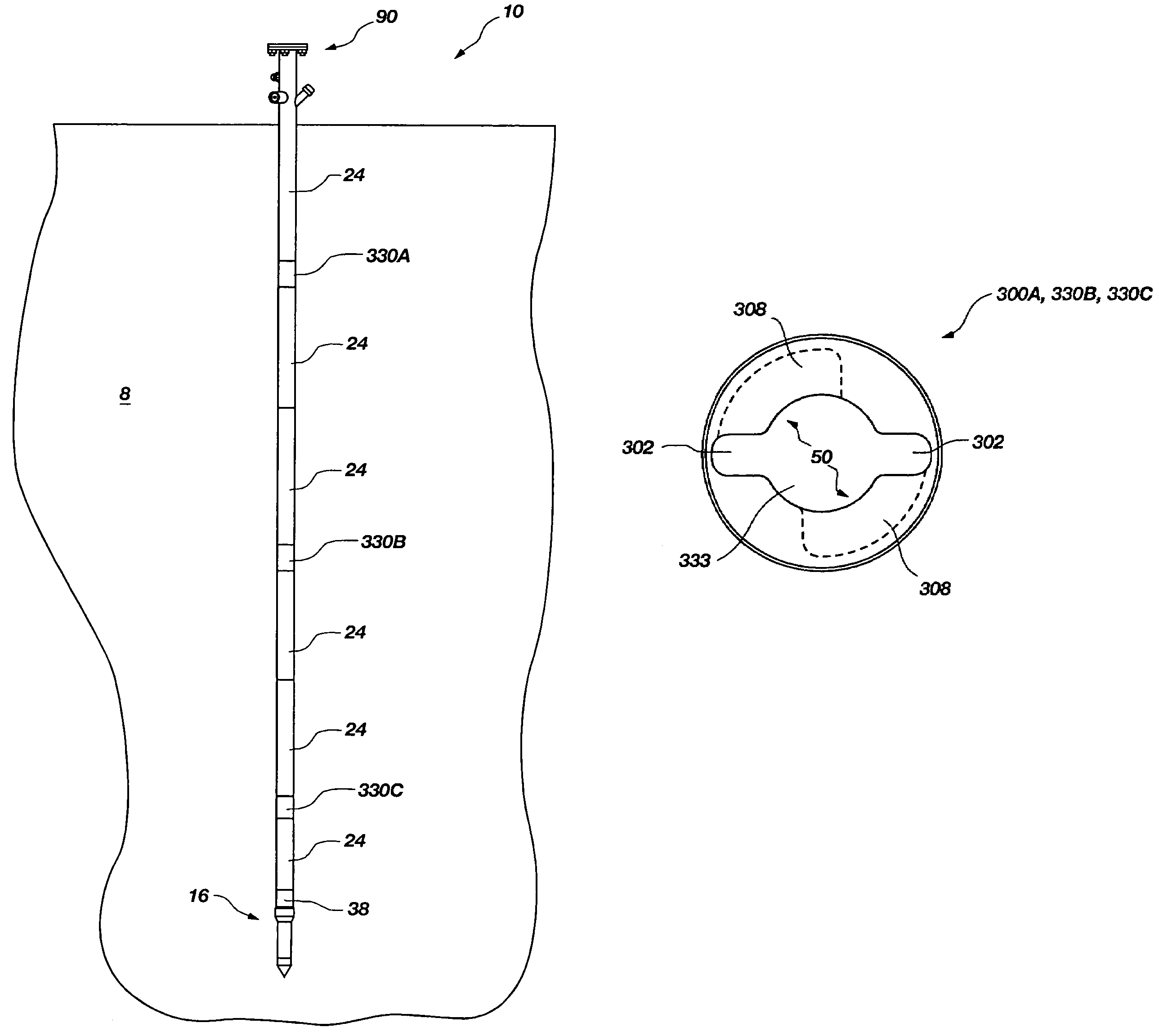
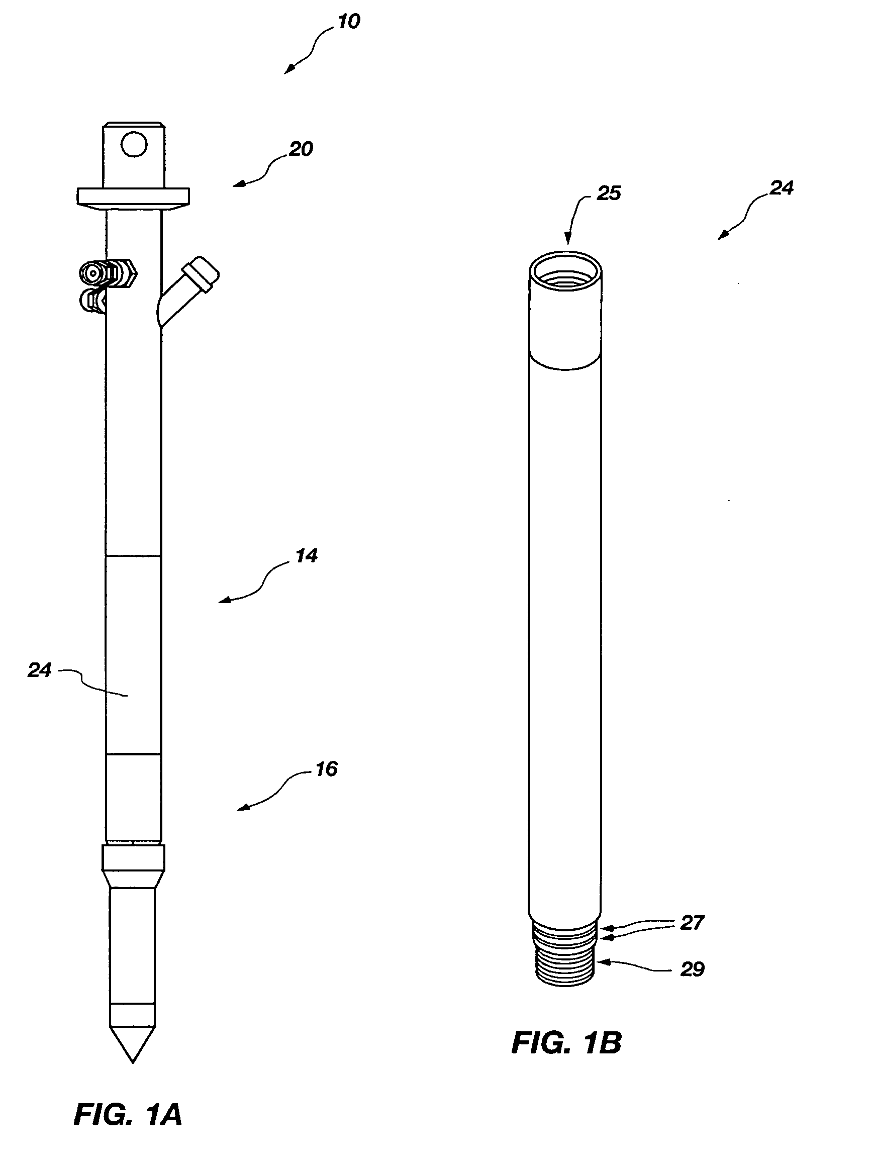
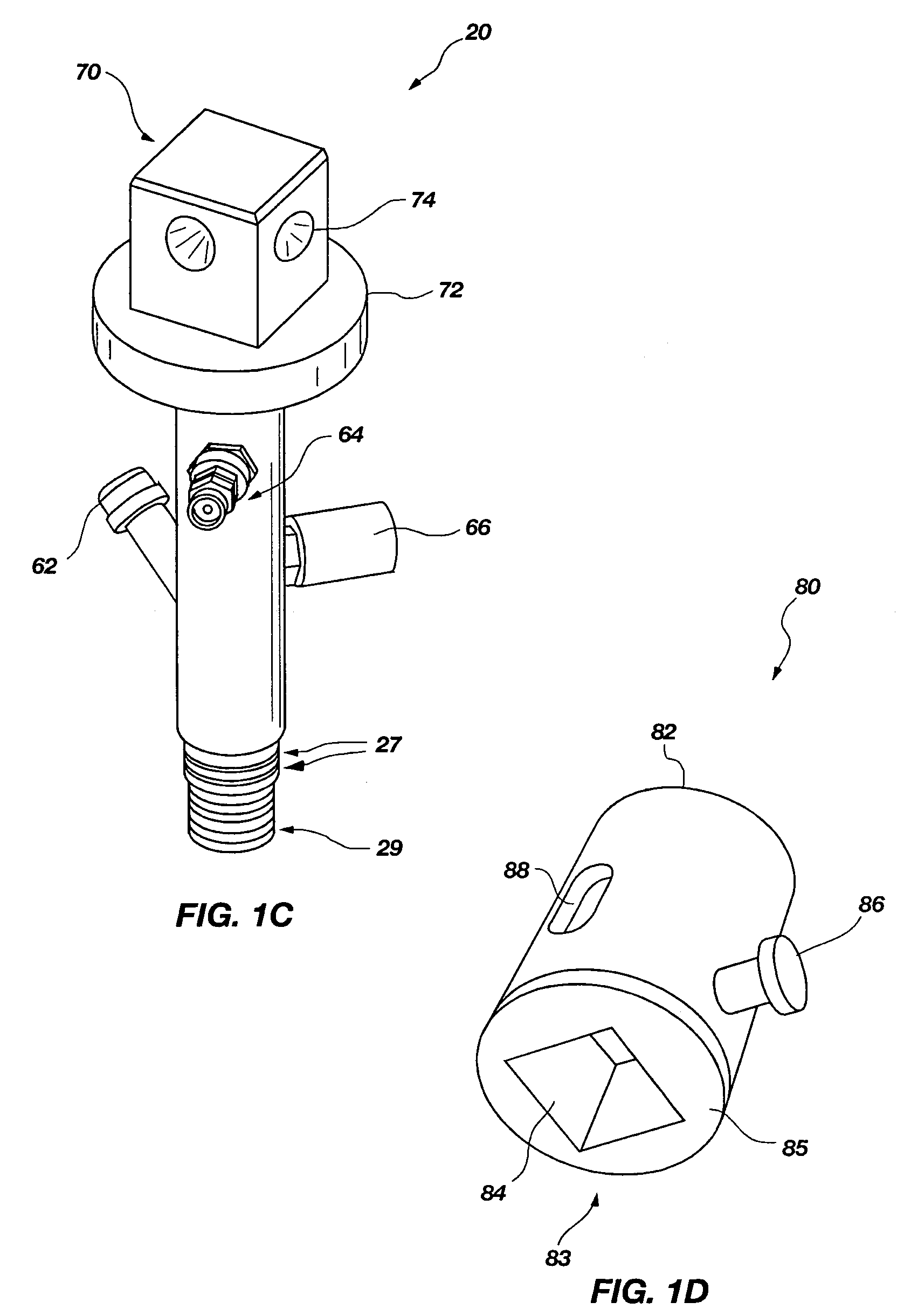
[0055]The present invention relates to methods and apparatuses for interaction with a region of a subterranean formation. For instance, the present invention relates to methods and apparatuses for measuring at least one characteristic of a region of a subterranean formation. Also, the present invention relates to methods and apparatus wherein an access casing assembly may be structured for selectively receiving, individually, a plurality of different sampling or interaction devices, configured for sampling or interaction with a subterranean formation, respectively.
[0056]The present invention allows for interaction with a region of a subterranean formation, such as, for instance, sampling or measuring thereof without the need for drilling, coring, or prior excavation. One method of the present invention includes placing an access casing assembly at least partially into a subterranean formation using direct push, sonic drilling, rotation, or a combination thereof and then selectively ...
PUM
Property
Measurement
Unit
length
aaaaa
aaaaa
height
aaaaa
aaaaa
height
aaaaa
aaaaa
Abstract
An access casing assembly structured for placement at least partially within a subterranean formation by forcing the access casing assembly thereinto, comprising a plurality of casing sections operably coupled to form a central elongated cavity for providing access to the subterranean region is disclosed. Further, a tip portion of the access casing assembly may include a porous filter through which liquid or gas may communicate with the central elongated cavity. Also, a receiving member or at least one engagement hub may form a portion of the central elongated cavity and may include an engagement feature configured for selectively and lockingly engaging a locking structure of a device to be positioned within the access casing assembly. Methods of use are disclosed. A tensiometer is disclosed including a chamber structured for allowing at least partially filling with a fluid subsequent to contact therewith.
Description
RELATED APPLICATIONS[0001]This application is a continuation-in-part of U.S. application Ser. No. 10 / 376,153, filed Feb. 28, 2003, now U.S. Pat. No. 6,920,780, issued Jul. 26, 2005, entitled TENSIOMETER, DRIVE PROBE FOR USE WITH ENVIRONMENTAL TESTING EQUIPMENT, AND METHODS OF INSERTING ENVIRONMENTAL TESTING EQUIPMENT INTO A SAMPLE, the disclosure of which is incorporated by reference herein in its entirety. This application is also a continuation-in-part of U.S. application Ser. No. 10 / 910,860, filed Oct. 31, 2002 (now abandoned), entitled INSERTION TUBE METHODS AND APPARATUS, which is a divisional of U.S. application Ser. No. 10 / 285,786, filed Oct. 31, 2002 (now abandoned), entitled INSERTION TUBE METHODS AND APPARATUS, the disclosure of each of which is incorporated by reference herein in its entirety. Further, this application is a continuation-in-part of U.S. application Ser. No. 10 / 973,710, filed Oct. 25, 2004, now U.S. Pat. No. 6,938,503, issued Sep. 6, 2005, entitled LYSIMETE...
Claims
Application Information
Patent Timeline
Application Date:The date an application was filed.
Publication Date:The date a patent or application was officially published.
First Publication Date:The earliest publication date of a patent with the same application number.
Issue Date:Publication date of the patent grant document.
PCT Entry Date:The Entry date of PCT National Phase.
Estimated Expiry Date:The statutory expiry date of a patent right according to the Patent Law, and it is the longest term of protection that the patent right can achieve without the termination of the patent right due to other reasons(Term extension factor has been taken into account ).
Invalid Date:Actual expiry date is based on effective date or publication date of legal transaction data of invalid patent.

