Passive evaporative emission control module

a technology of evaporative emission control and control module, which is applied in the direction of machine/engine, combustion-air/fuel-air treatment, and separation processes, etc., can solve the problems of air pollution, fuel spouted from the nozzle coming into violent contact with and agitating the fuel fuel bubbles in the fuel contained in the fuel reservoir, etc., to achieve simple design and increase design flexibility

Inactive Publication Date: 2007-12-25
MINIATURE PRECISION COMPONENTS
View PDF38 Cites 21 Cited by
  • Summary
  • Abstract
  • Description
  • Claims
  • Application Information

AI Technical Summary

Benefits of technology

[0010]The embodiments of the present invention provide several advantages. One such advantage is an evaporative emission control module that is simple in design and has a passive purge mechanism. The passive purge mechanism provides for purging of a hydrocarbon filter without the draw of airflow from an intake manifold or the systematic introduction of airflow into a purge canister.
[0011]Another advantage that is provided by an embodiment of the present invention is an evaporative emission control module that is directly attached to a fuel tank without the need for purge tanks, purge lines, or other fuel tank external devices.
[0012]Yet another advantage provided by the embodiments of the present invention is an evaporative emission control module that is integrally formed as part of or attached to a fuel tank and not part of a fuel cap. As such, the present invention provides increased design flexibility and an increased number of applications by which the present invention may be used.
[0013]Furthermore, the present invention provides an evaporative emission control module that has a fuel splash absorber, which prevents soaking of a hydrocarbon filter.

Problems solved by technology

Consequently, when the fuel cap is detached from the fuel inlet of the fuel reservoir, fuel vapor is forced out of the fuel reservoir into the outside air, causing air pollution.
In addition, when fuel is fed into the fuel reservoir from a fuel pump nozzle, the fuel spouted from the nozzle comes into violent contact with and agitates the fuel in the fuel reservoir.
This causes bubbles to form in the fuel contained in the fuel reservoir.
The collapsing of these bubbles causes further amounts of fuel vapor to be generated in the fuel reservoir, and this fuel vapor flows out from the fuel inlet, causing more air pollution.
These systems tend to be complex in design, and require an active purging of the vapor recovery canisters.
Not only is this an active system, but it also is limited in its ability to minimize vapor emissions, due to application feasible size constraints of the fuel cap.
Also, the fuel cap can be bulky and difficult or awkward to remove and replace from the fuel tank, as a result of the attached purge line.
Although the fuel cap may be appropriately sized, the fuel cap is incapable of minimizing fuel vapor emissions into the atmosphere.

Method used


Image

  • Passive evaporative emission control module
  • Passive evaporative emission control module
  • Passive evaporative emission control module

Examples


Embodiment Construction

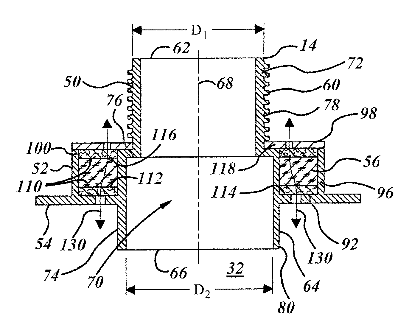
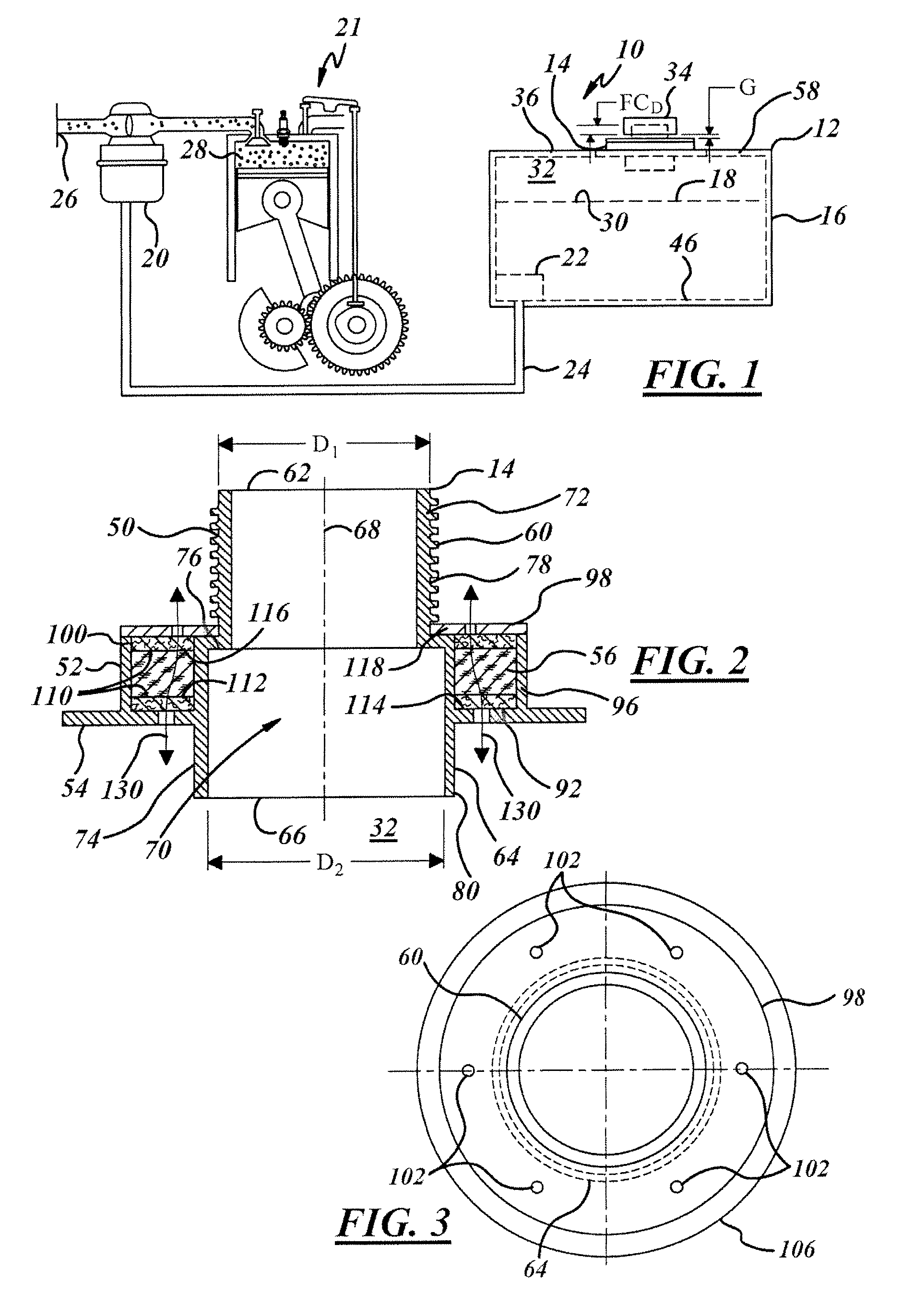
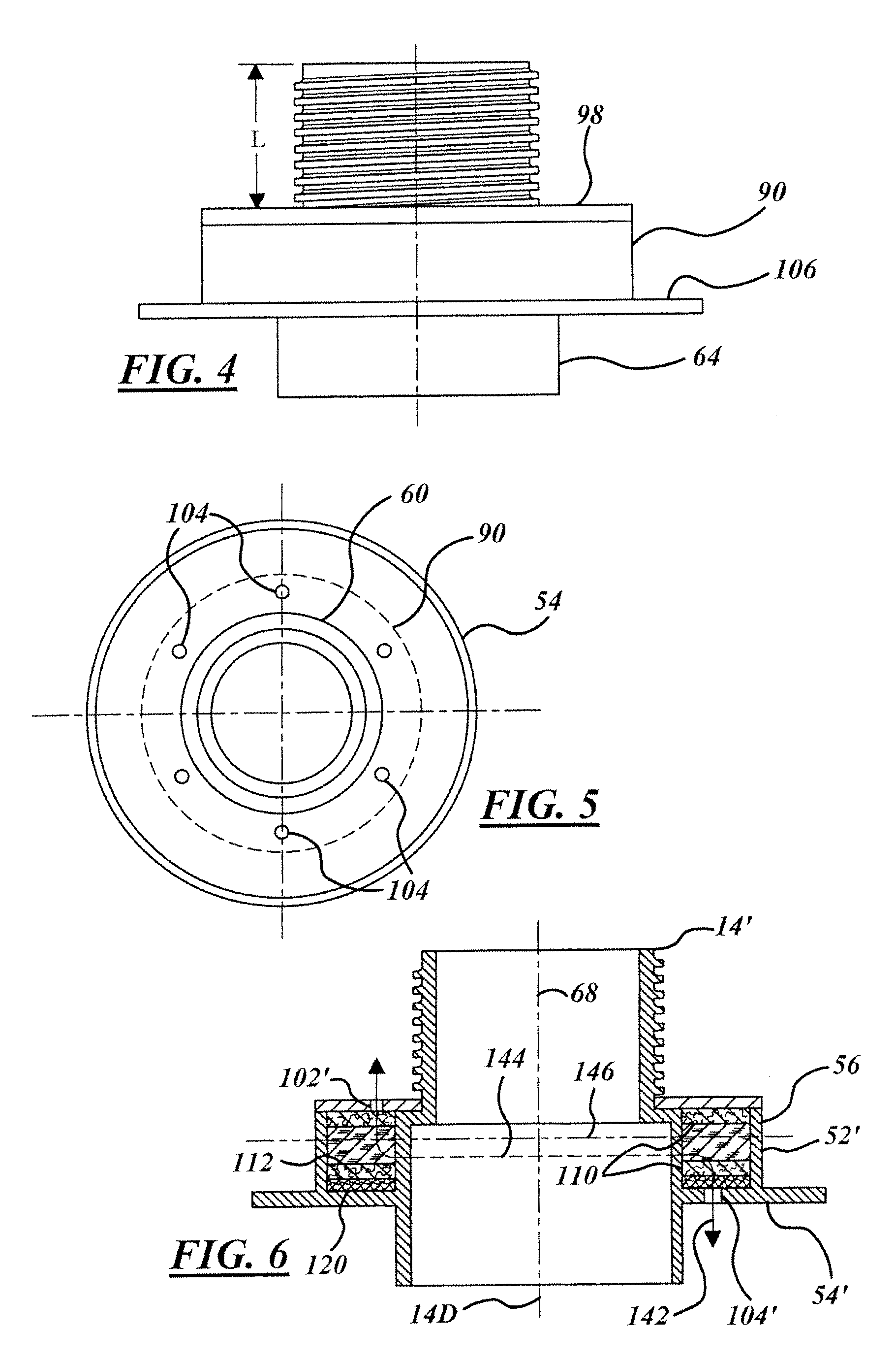
[0026]In the following figures, the same reference numerals will be used to refer to the same components. While the present invention is described primarily with respect to a passive evaporative emission control module for use in small displacement combustion engine applications, the present invention may be applied in and to various applications. The present invention may be applied to small displacement engine applications, such as to lawn mower applications, all-terrain vehicle applications, go-kart applications, trimmer applications, leaf blower applications, generators, power washers, chainsaw applications, snow blower applications, snow mobile applications, individual watercraft applications, and to various other small displacement engine applications known in the art. The present invention may also be applied to large displacement engine applications. The present invention may be utilized in association with various vehicle and non-vehicle applications. The present invention ...


PUM


Abstract

An emission control module (14) includes a housing (52) that includes an atmospheric air opening (102) and a vapor emission inlet (104) for communication with a vapor region (32) of a fuel reservoir (16). A hydrocarbon filter (56) is disposed between the atmospheric air opening (102) and the vapor emission inlet (104) to passively filter vapor emissions within the vapor region (32). The housing (52) is configured for purging of the hydrocarbon filter (56) due to a low-pressure draw from the vapor emission inlet (104).

Description

TECHNICAL FIELD[0001]The present invention relates to fuel tanks and to evaporative emission devices, circuits, and systems. More particularly, the present invention is related to a technique for passively controlling the amount of evaporative emissions emitted to the atmosphere from a fuel reservoir or the like.BACKGROUND OF THE INVENTION[0002]Internal combustion engines typically receive fuel that is contained within a fuel tank. An air space or vapor region exists, generally above the surface of the fuel, within the tank. The vapor region is composed of fuel evaporative emissions that can be under pressure. It is desired that the amount of such evaporative emissions contained within the tank be minimized for multiple reasons. One primary reason for such reduction is to minimize emissions of hydrocarbons into the atmosphere, and thus to minimize pollution of the atmosphere.[0003]A fuel tank assembly generally consists of a fuel reservoir, which has a fuel cap and may have a fuel n...

Claims


Application Information

Patent Timeline
Patent Type & Authority Patents(United States)
IPC IPC(8): F02M33/02
CPCB01D53/0431F02M37/0076F02M25/0854B01D2259/4516
Inventor CALLAHAN, DOUGLAS JOHNERTL, BRENT J.PRUZINSKIS, JURIS J.FARREY, MICHAEL P.BISHOP, HANS
Owner MINIATURE PRECISION COMPONENTS
Why Eureka
Try Eureka