Successive approximate capacitance measurement circuit

a capacitance measurement and circuit technology, applied in the field of electromechanical circuits, can solve the problems of 115/b>, which is a relatively complex and expensive componen

Inactive Publication Date: 2007-12-25
MONTEREY RES LLC
View PDF169 Cites 137 Cited by
  • Summary
  • Abstract
  • Description
  • Claims
  • Application Information

AI Technical Summary

Problems solved by technology

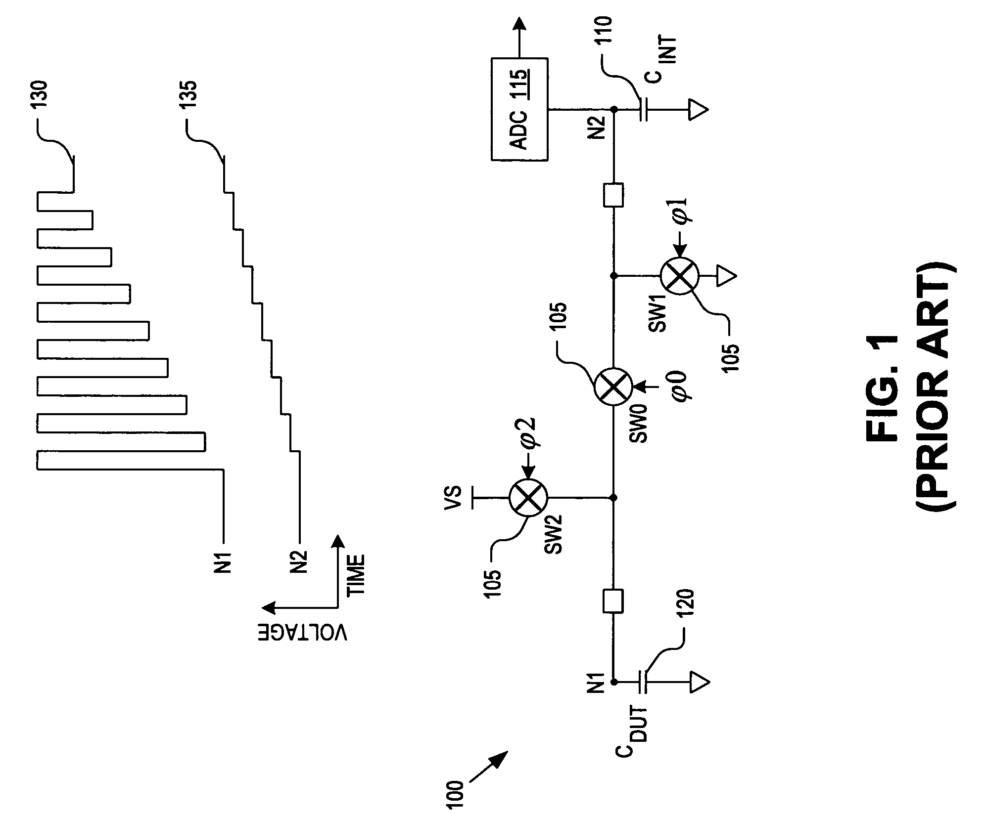
However, using a large CINT value requires a large number of charge transfer cycles to achieve a good capacitance measurement of CDUT.
Furthermore, capacitance sensor 100 uses ADC 115 which is a relatively complex and expensive component.

Method used


Image

  • Successive approximate capacitance measurement circuit
  • Successive approximate capacitance measurement circuit
  • Successive approximate capacitance measurement circuit

Examples


Embodiment Construction

[0013]Embodiments of an apparatus and method of operation for a capacitance measurement circuit are described herein. In the following description numerous specific details are set forth to provide a thorough understanding of the embodiments. One skilled in the relevant art will recognize, however, that the techniques described herein can be practiced without one or more of the specific details, or with other methods, components, materials, etc. In other instances, well-known structures, materials, or operations are not shown or described in detail to avoid obscuring certain aspects.

[0014]Reference throughout this specification to “one embodiment” or “an embodiment” means that a particular feature, structure, or characteristic described in connection with the embodiment is included in at least one embodiment of the present invention. Thus, the appearances of the phrases “in one embodiment” or “in an embodiment” in various places throughout this specification are not necessarily all ...


PUM


Abstract

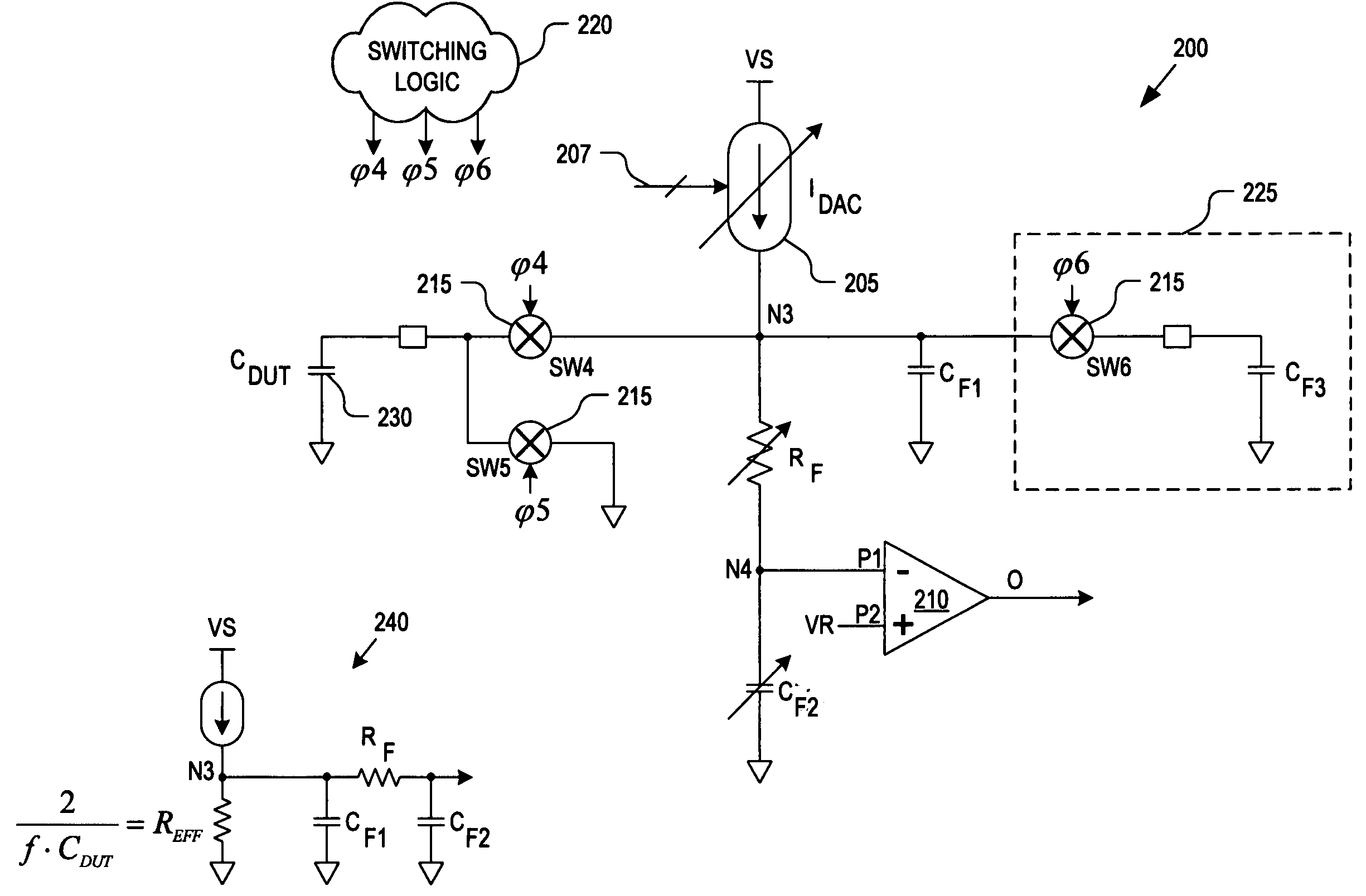
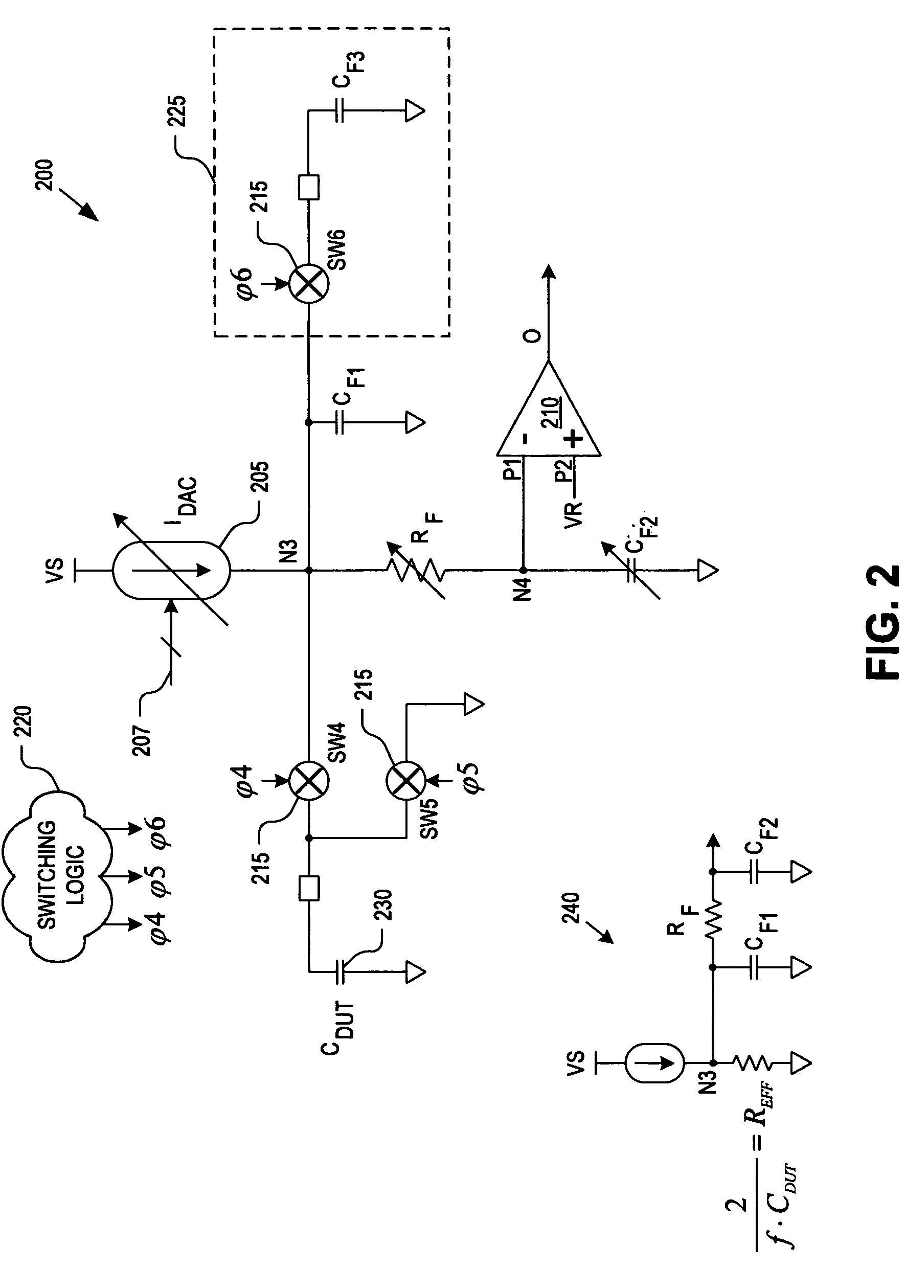
A capacitance measurement circuit includes a current source, a switch, and a comparator. The current source is coupled to drive a current through a circuit node. The switch is coupled to the circuit node to switch the current into a device under test (“DUT”) capacitor. The comparator includes first and second input ports. The comparator is coupled to compare a first voltage received on the first input port against a reference voltage received on the second input port. The first voltage is related to the current driven through the circuit node, a frequency at which the switch is switched, and a capacitance of the DUT capacitor.

Description

TECHNICAL FIELD[0001]This disclosure relates generally to electronic circuits, and in particular but not exclusively, relates to capacitance measurement circuits.BACKGROUND INFORMATION[0002]Capacitance sensors are used to implement a variety of useful functions including touch sensors (e.g., touch pad, touch dial, touch wheel, etc.), determining the presence of an object, accelerometers, and other functions. FIG. 1 illustrates a conventional capacitance sensor 100 including three switches 105 with control terminals φ0, φ1, and φ2, an integrating capacitor 110 having a capacitance CINT, and an analog to digital (“ADC”) converter 115. Capacitance sensor 100 may be used to sense changes in capacitance on a device under test (“DUT”) capacitor 120 having a changing capacitance CDUT.[0003]During operation, capacitance sensor 100 operates as follows to sense capacitance changes on DUT capacitor 120. First, integrating capacitor 110 is discharged to a ground potential by asserting control t...

Claims


Application Information

Patent Timeline
Patent Type & Authority Patents(United States)
IPC IPC(8): G01R27/26
CPCG01R27/2605
Inventor SNYDER, WARREN S.
Owner MONTEREY RES LLC
Why Eureka
Try Eureka