Method and system for time/motion compensation for head mounted displays

a head mounted display and time/motion compensation technology, applied in the field of telepresence systems, can solve problems such as areas of display for which no image information is available, and achieve the effect of removing some of the disorientation

Inactive Publication Date: 2007-12-25
CANADIAN SPACE AGENCY
View PDF15 Cites 142 Cited by
  • Summary
  • Abstract
  • Description
  • Claims
  • Application Information

AI Technical Summary

Benefits of technology

[0016]The invention relates to a method and apparatus that provides a wearer of an HMD with a stable frame of visual reference in cases where there may be time delays or unwanted motion within the visual capture/visual display systems.
[0017]According to the invention, in order to eliminate some of the disorientation caused by time delays in camera motion when a head motion occurs, an image shown on the display of a head-mounted displa

Problems solved by technology

Offsetting of the image results in areas of the di

Method used


Image

  • Method and system for time/motion compensation for head mounted displays
  • Method and system for time/motion compensation for head mounted displays
  • Method and system for time/motion compensation for head mounted displays

Examples


Embodiment Construction

[0041]The present invention is described with reference to telepresence systems operating over long distances such that significant time delays occur between head motion and image display of an image for a current head orientation. It is, however, equally applicable when a camera drive mechanism provides insufficient response rate to allow comfortable viewing of images during normal head motion. It is also applicable in situations where unwanted and unmodeled motion of the camera is possible, such as when the camera is mounted on a moving platform.

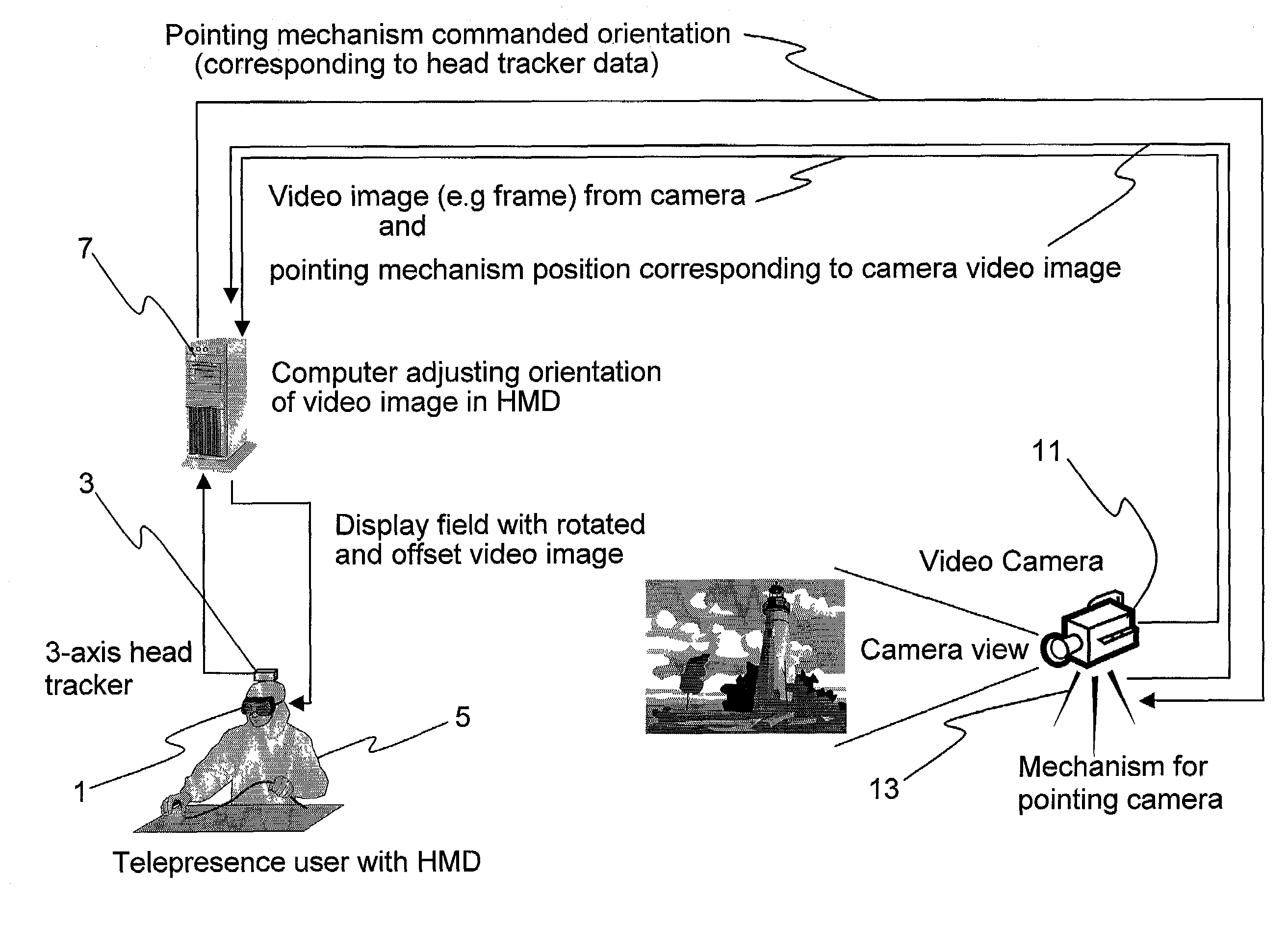
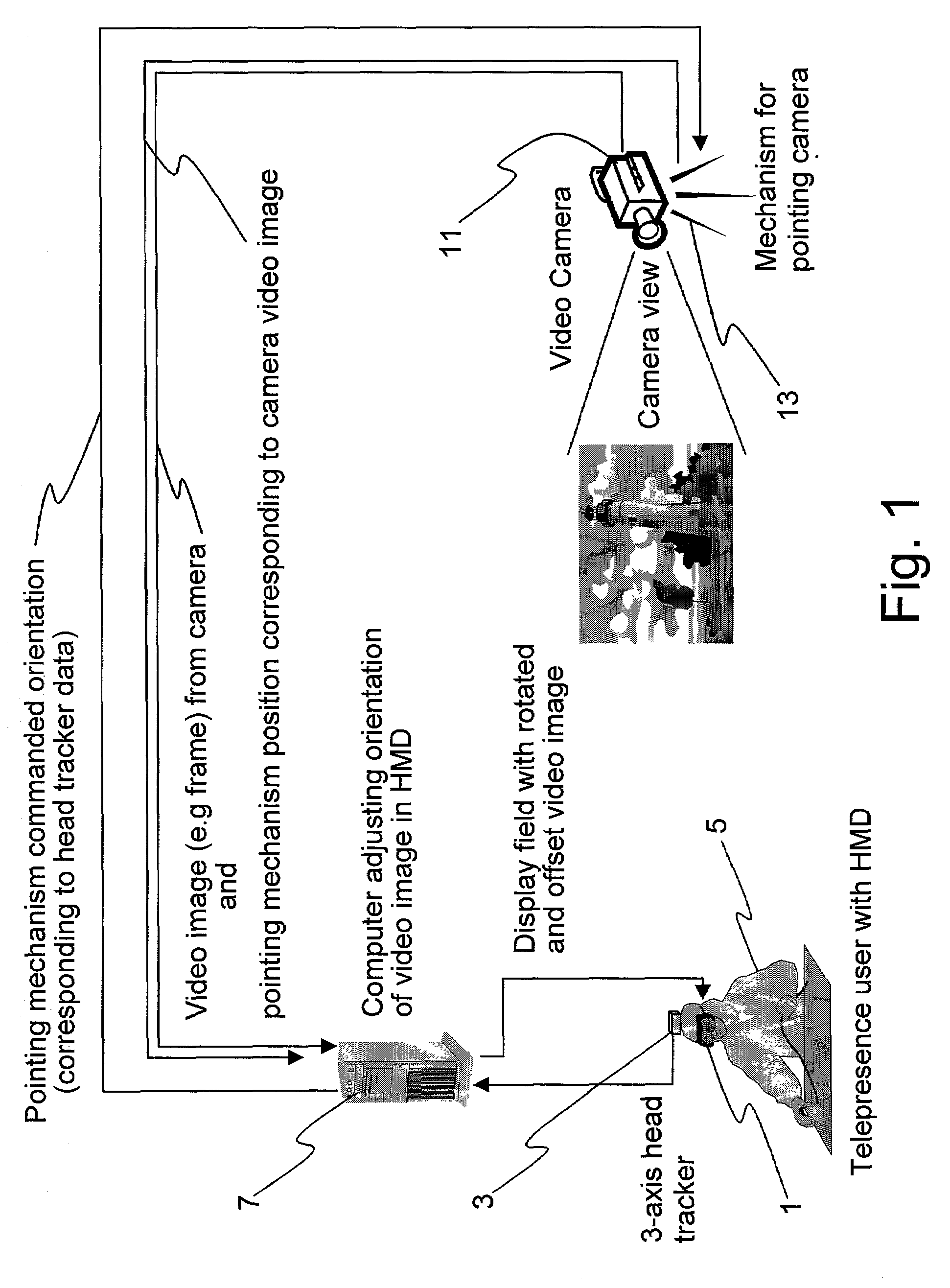
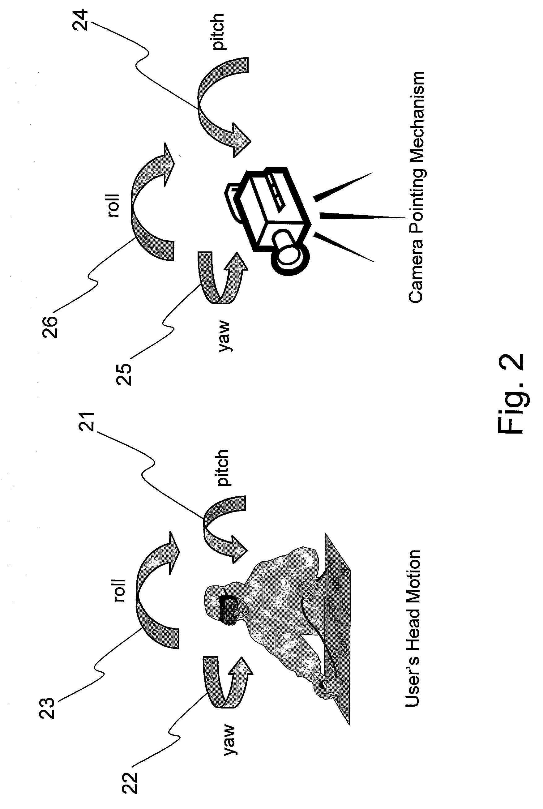
[0042]Referring to FIG. 1, a simplified block diagram of a telepresence system is shown. A head mounted display (HMD) 1 including a three-axes head tracker 3 is worn by an operator 5. The HMD 1 is coupled with a first computer 7 and provides to the first computer 7 HMD values for the HMD position in the form of pitch 21, yaw 22, and roll 23 angles of the HMD 1 as shown in FIG. 2. Of course, since the HMD 1 is being worn by an operator 5, t...


PUM


Abstract

A method and system for time-motion compensation for use with head mounted displays is disclosed. According to the method, a remote camera captures an image for display on a head-mounted display (HMD) including a viewing window. The image and camera position data is transmitted to a system including the HMD for display to a wearer of the HMD. The HMD position is determined. An offset between the HMD position and a known position of the HMD is determined as is an offset between the camera position and a known position of the camera. The image is offset relative to the viewing window of the image based on the difference between the two determined offsets.

Description

FIELD OF THE INVENTION[0001]The present invention generally relates to telepresence systems and more particularly relates to motion compensation in telepresence systems.BACKGROUND OF THE INVENTION[0002]The field of remote control has come a long way since the days of watching a model aircraft fly under the control of a handheld controller. Robotics and remote robotic manipulation have created a strong and pressing need for more remote and better remote control systems. Obviously, an ideal form of remote control involves providing an operator with all the sensations of operating the remote robot without the inherent dangers, travel, and so forth. In order to achieve this, a telepresence system is used.[0003]Telepresence systems are sensory feedback systems for allowing sensing and monitoring of remote systems. A typical telepresence sensor is a camera and a head mounted display. The system provides visual feedback from a remote location to an operator. For example, in a telepresence ...

Claims


Application Information

Patent Timeline
IPC IPC(8): G09G5/00G02B27/14H04N7/00H04N7/18H04N9/47
CPCG02B27/017H04N7/185H04N5/232G02B2027/0138G02B2027/0187H04N23/661H04N23/63H04N23/695
Inventor EDWARDS, ERIC C.
Owner CANADIAN SPACE AGENCY
Why Eureka
Try Eureka