Method and apparatus for assay based on light diffraction

a technology of light diffraction and assay, applied in the field of methods and apparatus for detecting analytes, can solve the problems of diffracted light incident on the substrate, not uniform scattering,

Inactive Publication Date: 2008-01-01
ANGLE EURO LTD +1
View PDF14 Cites 17 Cited by
  • Summary
  • Abstract
  • Description
  • Claims
  • Application Information

AI Technical Summary

Benefits of technology

[0048]processing means for analysing said diffracted light for presence of a diffraction image representative of binding of one...

Problems solved by technology

But because the probe molecules are laid out in a predetermined pattern, lig...

Method used


Image

  • Method and apparatus for assay based on light diffraction
  • Method and apparatus for assay based on light diffraction
  • Method and apparatus for assay based on light diffraction

Examples


example 1

Preparation of Patterned Substrate By Microcontact Printing

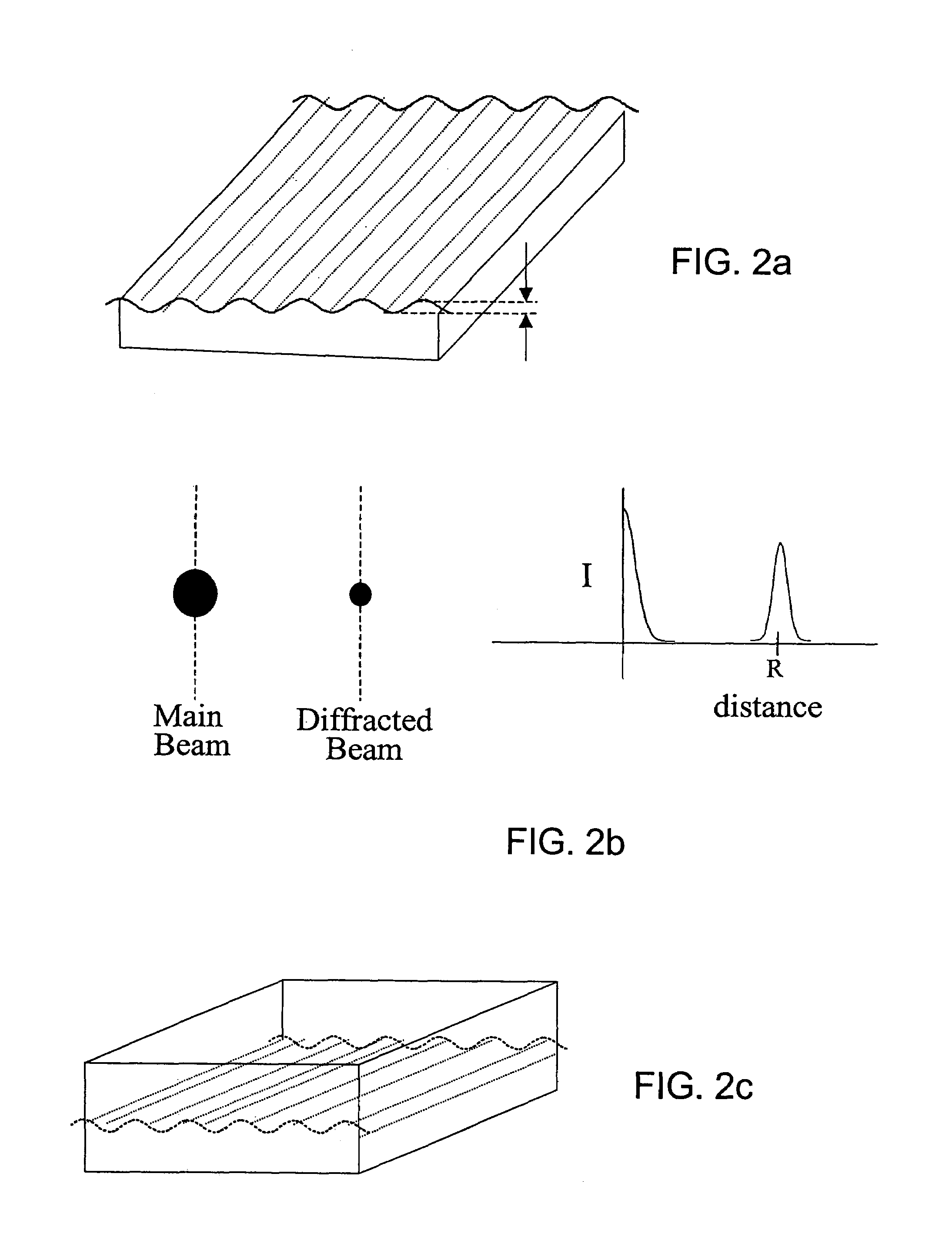
[0099]The substrates were patterned by microcontact printing essentialy following the procedure described in Bernard, A; Delamarche, E.; Schmid, H.; Michel, B.; Bosshard, H. R.; Biebuyck, H.; “Printing Patterns Of Proteins” Langmuir (1998), 14, 2225-2229. For evenly-spaced masters (diffraction grating), electron microscope grids or masters prepared by standard photolithography were used; otherwise various diffractive optics (Thor Labs) were employed. The poly(dimethylsiloxane) (PDMS) stamps were fabricated by using typically 10% crosslinking (Sylgard 184 Silicone elastomer kit, Dow Corning Corporation purchased from Paisley Products, Ontario Canada) and curing at 50-60° C. for 14-18 h. The PDMS stamps prepared in this manner have a diffractive surface of ˜50 mm2. The PDMS stamp was cleaned by sonication in a 2:1 solution of distilled and deionized water (ddH2O) / ethanol for 5-10 min, followed by drying under a stream of nitro...

example 2

Signal Measurement

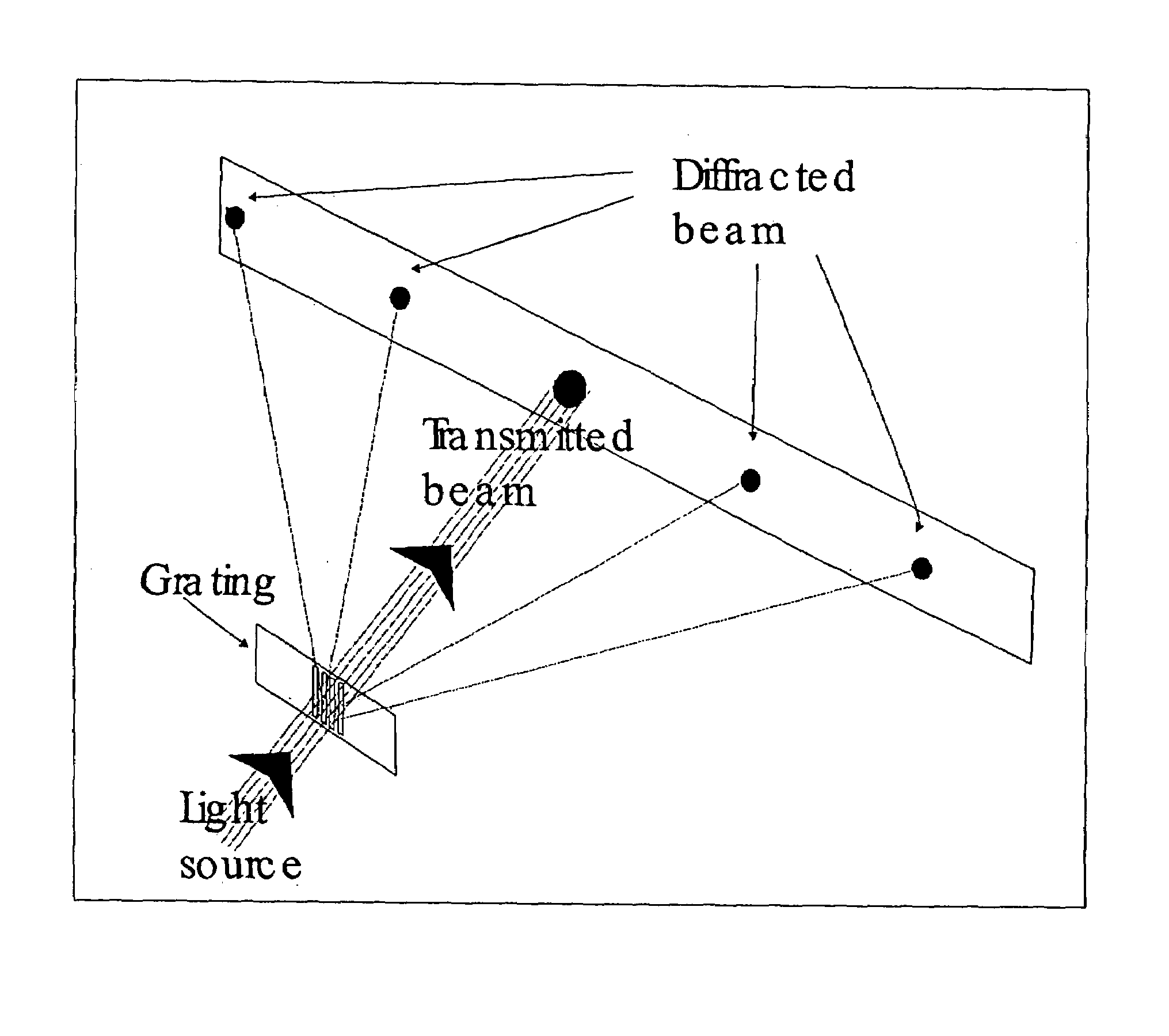
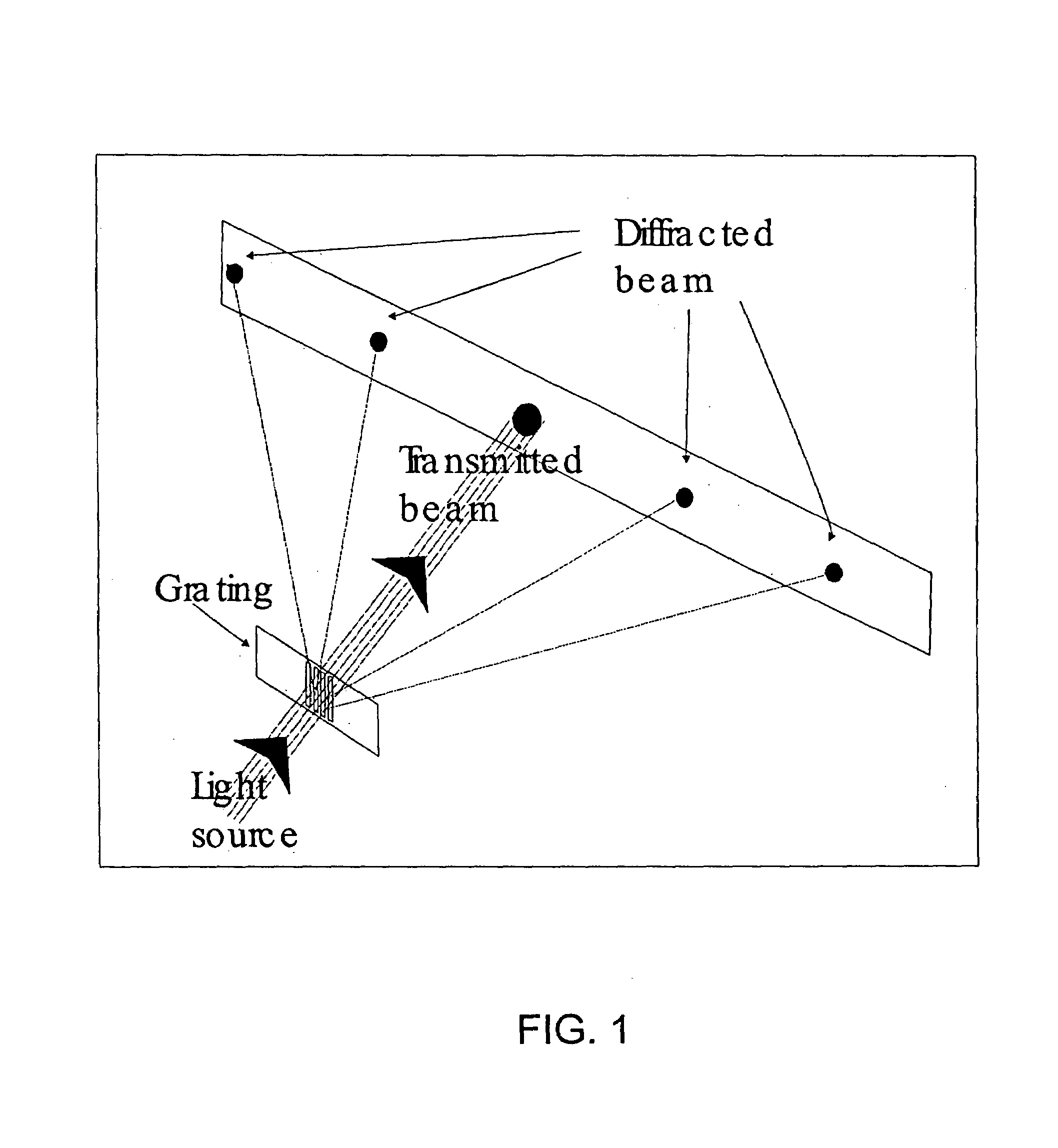
[0101]The substrate was illuminated with either a Nd:YVO4 laser (lambda=532 nm) or a red diode laser (lambda=650 nm). The diffraction image of crossed-stamped substrates resulting from illumination by either laser can be visually observed in transmission or reflection mode prior to addition of analyte. For visual and photographic signal detection, the intensity of the diffracted light was reduced to the point when the diffraction image was no longer discernible by eye using a neutral density filter before the addition of analyte. For electronic signal detection, the intensity was reduced with a neutral density filter to a small, but measurable value to maximize the signal range of the detection device before the addition of analyte.

example 3

“Dry” Measurement

[0102]In the “dry” measurement scheme, the substrate was immersed in a solution containing the analyte for the specified period of time. The substrate was then removed from the analyte solution, washed with PBS (2 mL) and ddH2O (2 mL), and dried under a stream of N2. The substrate was illuminated with a laser and a visible diffraction image could be discerned by eye and the intensity measured using a CCD linear array or CCD area array detector hooked up to a computer. Alternatively, a photomultiplier tube mounted on an x-y translation stage was used to measure the signal intensity of a specific spot on the diffraction image by moving it across the spot while recording the intensity on an oscilloscope.


PUM


Abstract

The present invention relates to a method and apparatus for detecting analytes in a medium, and more particularly the present invention relates to an assay based on light diffraction which appears or changes upon the binding of analytes to their specific receptors laid out in patterns on a substrate, which has high sensitivity due to the appropriate choice of such patterns. The present invention is based on the principle that the pattern of recognition elements, which gives rise to the diffraction of the incident light in a diffraction-based assay, can be chosen in such a way so as to facilitate detection, and to enhance the signal to be detected compared to known gratings such as parallel straight lines. In one aspect the substrate itself has a surface topography designed to enhance the diffraction pattern signals. In another aspect the substrate is a diffractive optic element having the analyte-specific receptors affixed to the optic element. In another aspect the diffractive optic element is used as a master stamp for producing patterns of analyte-specific receptors which give the signal enhancements.

Description

CROSS REFERENCE TO RELATED UNITED STATES PATENT APPLICATION[0001]This patent application relates to United States Provisional patent application Ser. No. 60 / 318,624 filed on Sep. 13, 2001, entitled METHOD AND APPARATUS FOR ASSAY BASED ON LIGHT DIFFRACTION.FIELD OF THE INVENTION[0002]The present invention relates to a method and apparatus for detecting analytes in a medium, and more particularly the present invention relates to an assay based on light diffraction which appears or changes upon the binding of analytes to their specific receptors laid out in patterns on a substrate, which has high sensitivity due to the appropriate choice of such patterns.BACKGROUND OF THE INVENTION[0003]In many instances, it is desirable to determine the presence and the amount of a specific material in solution (the ‘medium’). Surface-based assays rely on the interaction of the material to be assayed (the ‘analyte’) with a surface that results in a detectable change in any measurable property. (For th...

Claims


Application Information

Patent Timeline
IPC IPC(8): C12M1/34G01N21/05G01N21/47G01N33/543
CPCG01N33/54373Y10S435/808Y10S436/805
Inventor GOH, M. CYNTHIALOO, RICHARDGOH, JANE B.MCALONEY, RICHARD
Owner ANGLE EURO LTD
Why Eureka
Try Eureka