
Vehicle control method and vehicle control apparatus

a vehicle control and control method technology, applied in the direction of process and machine control, braking systems, instruments, etc., can solve the problems of not revealing the cooperation of steering and braking, or the cooperation of steering and driving, and the force generated by the wheel cannot be optimized, so as to optimize the effective road friction of each wheel, the effect of effective road friction and effective road friction

Inactive Publication Date: 2008-01-01
TOYOTA CENT RES & DEV LAB INC
View PDF25 Cites 27 Cited by
  • Summary
  • Abstract
  • Description
  • Claims
  • Application Information

AI Technical Summary

Benefits of technology

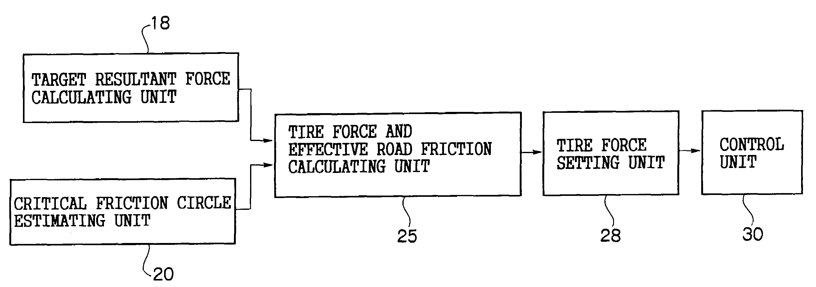
The present invention provides a method for calculating a target resultant force to be applied to a vehicle body in order to achieve the desired vehicle body motion. The method takes into account various parameters such as the critical friction circle of each wheel, the physical quantity relating to the tire force of each wheel, and the constraint of a maximum resultant force. The method calculates a physical quantity that optimizes the effective road friction of each wheel, and controls the braking force, driving force, and steering angle of each wheel accordingly to achieve the desired vehicle body motion. The invention also provides a system for controlling the vehicle's motion based on the target resultant force and the physical quantity relating to the tire force.

Problems solved by technology

This related art does not disclose cooperation of steering and braking, or cooperation of steering and driving.
However, in an actual vehicle, critical friction is generated between a wheel and a road surface, and lateral force may be decreased by increasing braking force.
However, the above related art does not mention the cooperation at all, such as adjusting steering according to braking or driving.
As a result, a problem arises in that the force generated by the wheel cannot be optimized.

Method used


Image

  • Vehicle control method and vehicle control apparatus
  • Vehicle control method and vehicle control apparatus
  • Vehicle control method and vehicle control apparatus

Examples


Embodiment Construction

[0035]A preferred embodiment of the present invention will be described in detail below with reference to the drawings. First, a principle of cooperative control of steering and braking in a vehicle which enables independent steering and braking of four wheels, and a principle of cooperative control of steering and driving in a vehicle which enables independent steering and driving of four wheels will be described.

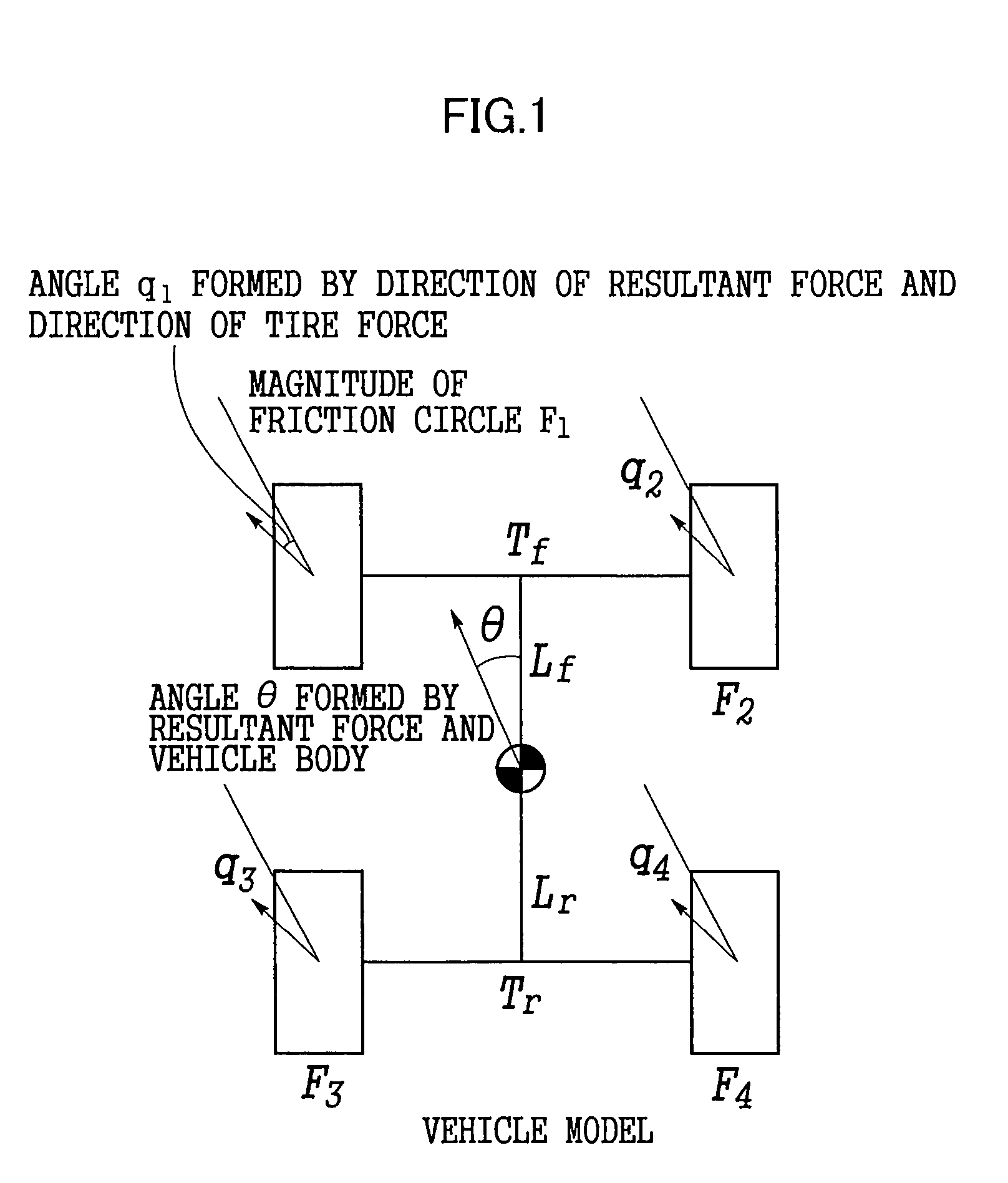
[0036]In a motion model of a four-wheel-drive vehicle shown in FIG. 1, a direction θ in which a force is applied to a vehicle body as a resultant force, which is the sum of forces generated by four wheels, in order to obtain a vehicle body motion that a driver desires, and the magnitude (radius) Fi of a critical friction circle of each wheel (wherein i=1 to 4) are known. (i=1 represents a left front wheel, i=2 represents a right front wheel, i=3 represents a left rear wheel, and i =4 represents a right rear wheel.) In this case, the direction of the tire force which maximi...


PUM


Abstract

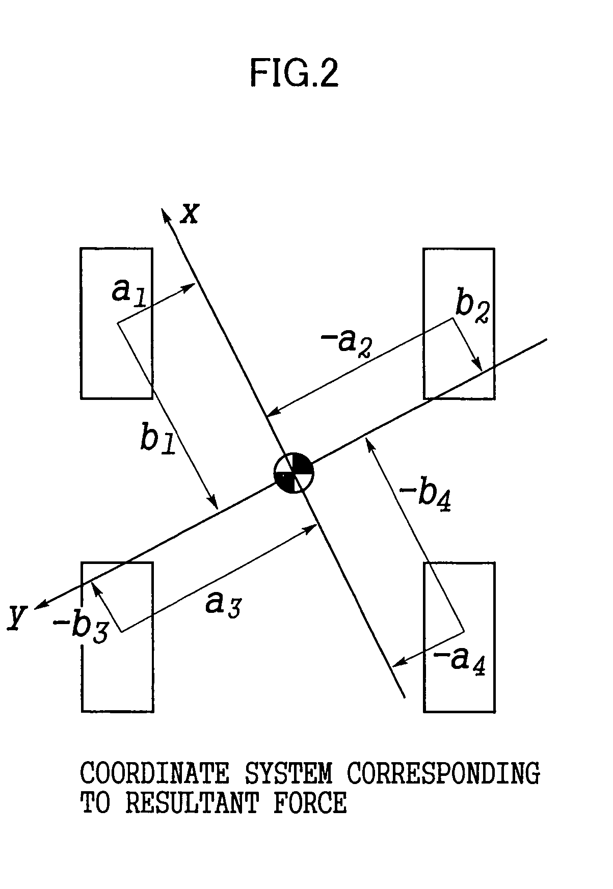
A target resultant force to be applied to a vehicle body is calculated, the magnitude of a critical friction circle of each wheel is estimated, and a critical resultant force is estimated from the estimated magnitude of the critical friction circle. Subsequently, a ratio of the target resultant force to a critical resultant force is set as an effective road friction, and the magnitude of a tire force is set by using the magnitude of the critical friction circle and the effective road friction. The direction of the tire force of each wheel to be controlled is set based on the sum of products, which are calculated for all other wheels, of a distance from the position of the wheel to be controlled to the position of the other wheel in a direction of the resultant force, and the magnitude of the tire force of the other wheel. Cooperative control of steering and braking or steering and driving of each wheel to be controlled is performed based on the magnitude and direction of the tire force which have been set.

Description

CROSS-REFERENCE TO RELATED APPLICATION[0001]This application claims priority under 35 USC 119 from Japanese Patent Application Nos. 2003-24177 and 2003-385973, the disclosures of which are incorporated by reference herein.BACKGROUND OF THE INVENTION[0002]1. Field of the Invention[0003]The present invention relates to a vehicle control method and a vehicle control apparatus. Specifically, the present invention relates to a method and an apparatus for controlling a vehicle which can control a tire force, that is, a force generated between a tire and a road surface, by independently controlling each steering angle and braking force of four wheels, and a vehicle which can control a tire force by independently controlling steering angles and braking forces of front wheels and those of rear wheels.[0004]2. Description of the Related Art[0005]A technique for separately controlling four wheels and steering angles thereof has been known, as disclosed in Japanese Patent Application Laid-Open ...

Claims


Application Information

Patent Timeline
Patent Type & Authority Patents(United States)
IPC IPC(8): B60T8/24B60R16/02B62D6/00B60T8/172B60T8/175B60T8/1755B60T8/1763B60T8/1764B60T8/58B60W10/00B60W10/04B60W10/06B60W10/18B60W10/184B60W10/20B60W30/02B60W40/064B60W40/068B62D5/04B62D7/14B62D101/00B62D109/00B62D111/00B62D113/00B62D119/00B62D137/00G06F7/70G06G7/76
CPCB60T8/1755B60W10/04B60W10/18B60W10/20B60W30/02B60W40/064B60W40/068B62D6/002B62D6/006B60T2260/02B60T2260/022
Inventor ONO, EIICHI
Owner TOYOTA CENT RES & DEV LAB INC
Learn More