

Force control joint device capable of keeping output force constant
A technology of outputting force and joints, applied in the field of robotics, can solve problems such as unstable contact pressure
- Summary
- Abstract
- Description
- Claims
- Application Information
AI Technical Summary
Problems solved by technology
Method used
Image

Examples
Embodiment Construction
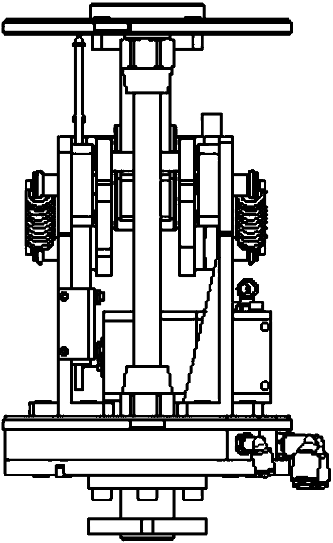
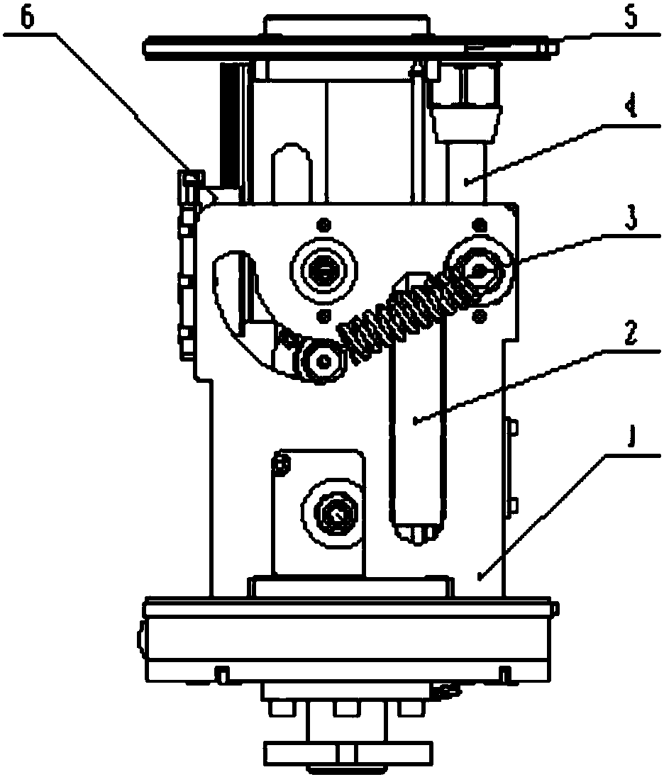
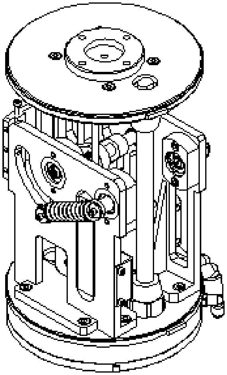
[0029] Figure 1 and figure 2 What is shown is a force-controlled joint device for keeping the output force constant according to an embodiment of the present invention, including:
[0030] base (1), displacement sensor (2), elastic mechanism component (3), pneumatic muscle structure component (4), output end (5), guide rail component (6),
[0031] Among them, the base (1) provides support for the elastic mechanism component (3), the displacement sensor (2), the pneumatic muscle structure component (4) and the guide rail component (6), and can adjust the air pressure in the pneumatic muscle structure component (4) ; The output end (5) includes the upper joint (28) of the pneumatic muscle structure component and the bolt hole (29) of the connecting rod seat; the elastic mechanism component (3), and the pneumatic muscle structure component (4) work together to control the force control joint The output of the device; the force-displacement sensor (2) is used to measure the join...
PUM
 Abstract
Description
Claims
Application Information