Sanitary liquid pressure regulator

a technology of liquid pressure regulator and regulator, which is applied in fluid pressure control, process and machine control, instruments, etc., can solve the problems of not being able to achieve taking excessive time to arrive at the appropriate target liquid pressure, and improving the performance of conventional industrial pressure regulator valves that are not typically suitable for use in sanitary valves

Inactive Publication Date: 2005-08-16
ARLINGHAUS JR JOSEPH WILFRED
View PDF17 Cites 9 Cited by
  • Summary
  • Abstract
  • Description
  • Claims
  • Application Information

AI Technical Summary

Problems solved by technology

The feedback controller can work well, but can take excessive time to arrive at the appropriate target liquid pressure.
Typical tactics to improve performance in conventional industrial-style pressure regulator valves are not typically suitable for use in sanitary valves For example, the pressure reducing valve of the prior art shown in U.S. Pat. No. 6,371,156 shows a typical pilot valve correction scheme used in regulating valves.
The cleanability requirements of the sanitary industries can render this kind of valve render inappropriate for sanitary products since many of the valve features, such as the pilot lines 26 and 28 would be difficult to clean.

Method used


Image

  • Sanitary liquid pressure regulator
  • Sanitary liquid pressure regulator
  • Sanitary liquid pressure regulator

Examples


Embodiment Construction

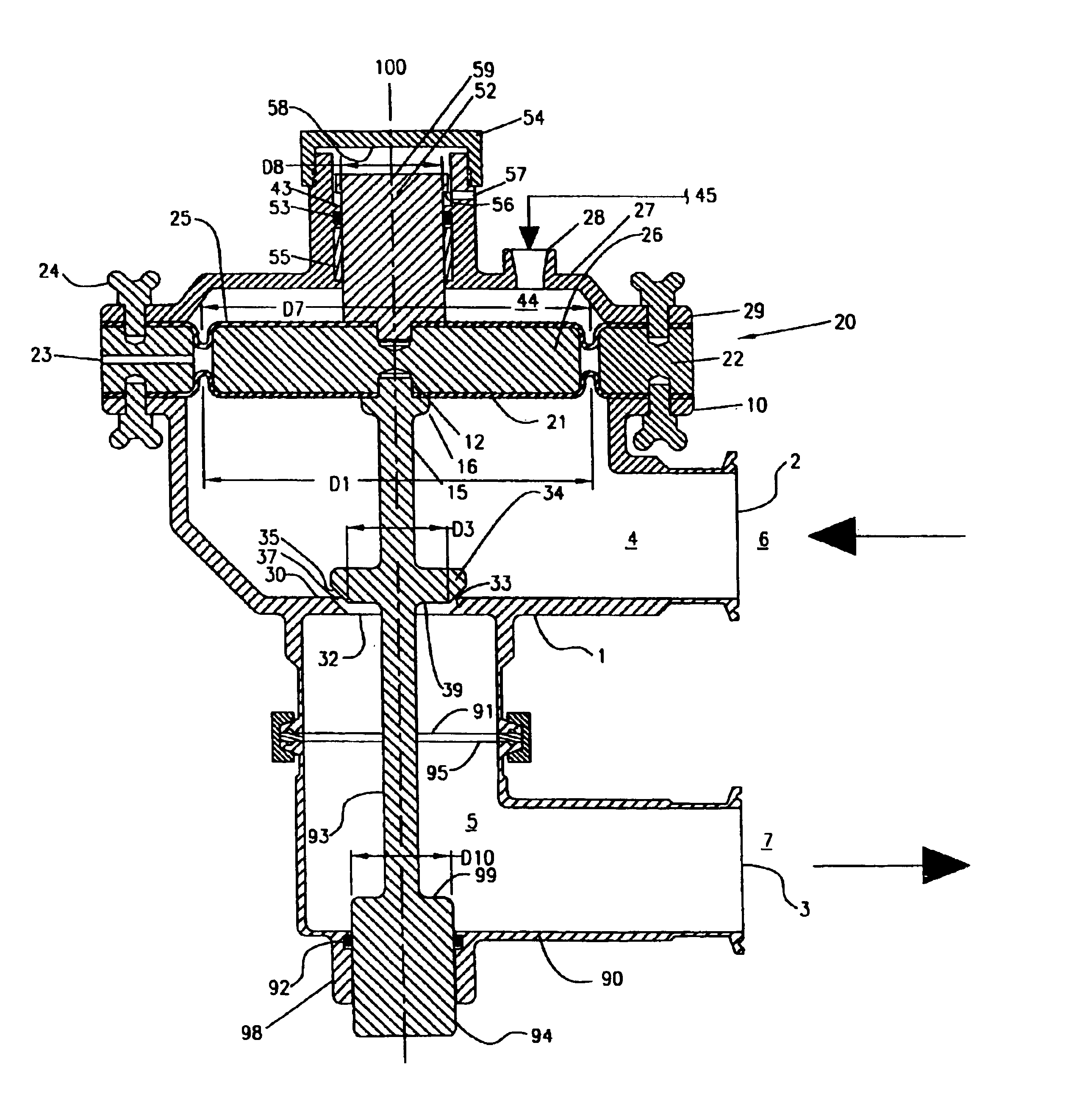
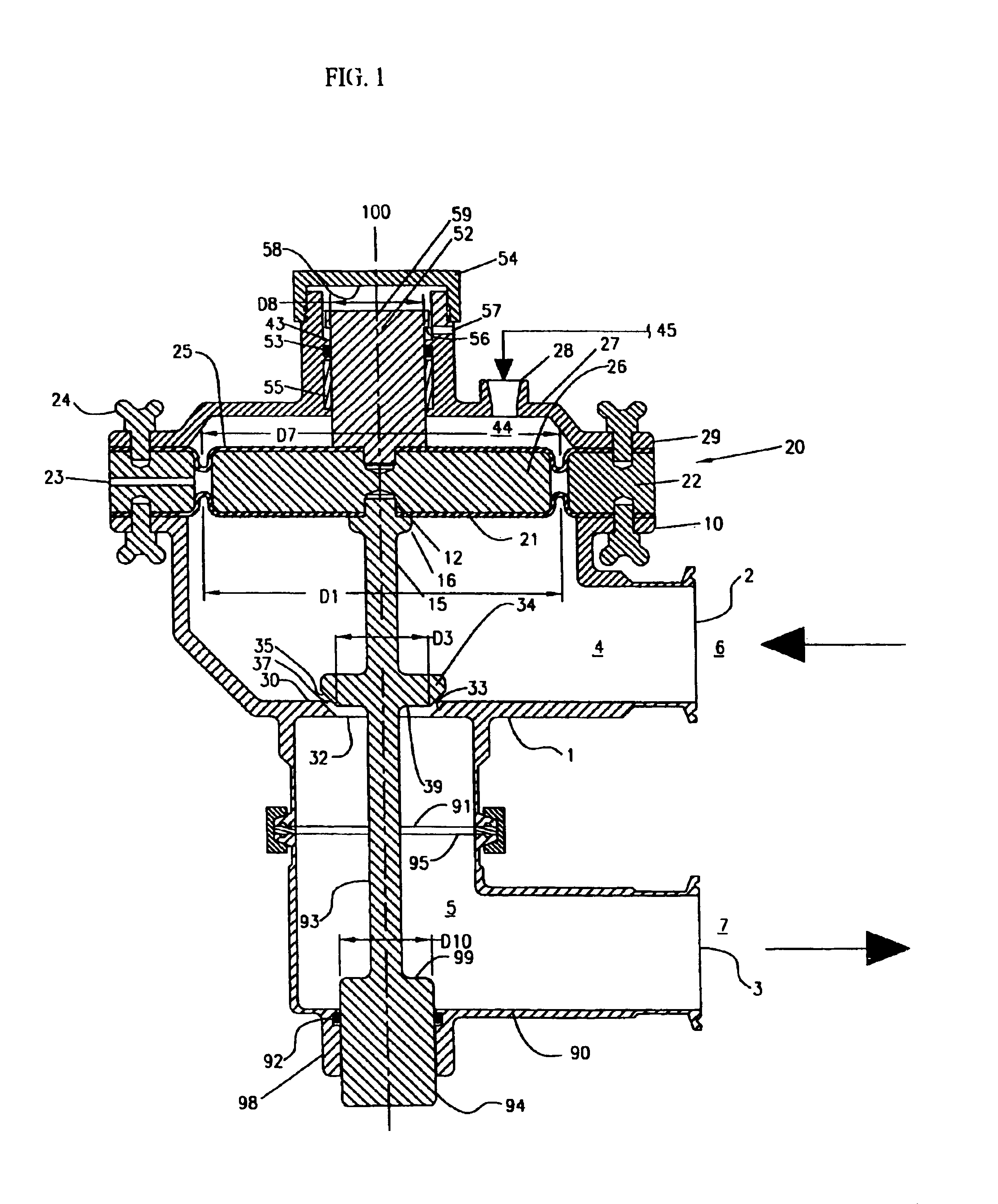
[0043]FIG. 1 shows a liquid pressure building regulator valve of the present invention. A liquid pressure building regulator can be characterized by its control of the liquid product pressure on the upstream (inlet) side. The means for controlling the liquid pressure (here, a diaphragm assembly 20) is in direct fluid communication with the upstream liquid side 6. The liquid pressure building regulator has a liquid housing 1 defining a liquid flow passage having a flow inlet 4 associated with a liquid inlet passage 2 and a flow outlet 5 associated with a liquid outlet passage 3. An orifice means 30 is positioned between the liquid inlet 4 and the liquid outlet 5. The orifice means 30 comprises a seat 33 that defines an opening 32 through which liquid communication is provided between the inlet 4 and the outlet 5. The orifice means 30 can permit, restrict, or shut off fluid flow, in response to the positioning of a valve plug 34, through a flow orifice 37 defined by the annular area b...


PUM


Abstract

A pressure building regulator having a pressure receiving means in liquid communication with the liquid outlet passage, upon which a liquid in the liquid outlet passage can exert a balancing force, and a means for communicating the balancing force to the diaphragm opposing the backpressure force. The liquid pressure regulator typically employs a balancing piston which can transfer pressure fluctuations in the flow outlet into an equal and opposite force on the valve plug, and results in a net force of zero in the diaphragm plate. As a result, changes in the liquid pressure downstream of the valve plug only nominally, and typically negligibly, affect the upstream control of the liquid product.The invention also includes a pressure reducing regulator, configured with a balancing piston which can transfer pressure fluctuations in the flow outlet into an equal and opposite force on the valve plug, and results in a net force of zero in the diaphragm plate.The invention further provides a liquid pressure regulator having a differential diaphragm plate having a rigid structure, having a first side of a first surface area, and an opposed second side of a second surface area, where the first surface area and the second surface area are unequal. The differential diaphragm plate permits the use of conventional compressed air control regulators with the liquid pressure regulator to control a high pressure liquid system more accurately.

Description

FIELD OF THE INVENTION[0001]The present invention relates to liquid pressure reducing regulators and liquid pressure building regulators for the sanitary industry.BACKGROUND OF THE INVENTION[0002]The food, beverage, and biopharmaceutical industries, which can be collectively referred to as the sanitary industry, have special needs in the design of the liquid piping systems in manufacturing facilities, and in particular of automatic liquid flow and pressure control valves. The safety and purity of these sanitary products require that the liquid products be free from spoilage or contamination by outside agents, including cleaning solvents or solutions used during the system cleanout, and control fluids used during the manufacturing process. In the sanitary industry, the cleanability of a valve in a liquid piping system represents an important feature. Cleanability relates to the ability to thoroughly and effectively clean a valve in-place (i.e., without being physically removed from t...

Claims


Application Information

Patent Timeline
Patent Type & Authority Patents(United States)
IPC IPC(8): G05D16/06G05D16/10G05D16/04
CPCG05D16/0655G05D16/185G05D16/2093G05D16/024G05D16/2095Y10T137/7782Y10T137/7796Y10T137/7801
Inventor ARLINGHAUS, JR., JOSEPH WILFRED
Owner ARLINGHAUS JR JOSEPH WILFRED
Why Eureka
Try Eureka