Slip ring positive z force liquid isolation fixture permitting zero net force on workpiece

a liquid isolation fixture and positive z force technology, applied in the direction of instruments, specific gravity measurement, magnetic property measurement, etc., to achieve the effect of wide operating zon

Inactive Publication Date: 2009-04-02
GLOBALFOUNDRIES INC
View PDF12 Cites 9 Cited by
  • Summary
  • Abstract
  • Description
  • Claims
  • Application Information

AI Technical Summary

Benefits of technology

[0010]An advantage of the present invention is the fact that Z-axis direction forces applied to a DUT are cancelled. The present invention differs from the teachings of the Sherstinsky patent in that it provides dual contiguous seals along the entire wafer edge, and is designed to provide uniform, equal and opposite Z-axis forces at every point where the seals contact the edge of the DUT.
[0011]In comparison with U.S. Pat. No. 6,569,302 of Steinrücke, a primary element of the present invention is the strict adherence to perfectly aligned and identical seals to net zero Z-axis direction force.
[0012]An important feature of the present invention is that a pool of water is to be in contact with an upwardly facing surface of a workpiece, e.g. a semiconductor wafer, whereas a downwardly facing surface of the workpiece is protected by an isolated air pocket. There is the problem that a resultant differential force is created by a pool of water and an air pocket. We have found that it is necessary to compensate for that differential force. In accordance with the present invention, compensation for the differential force is provided by a net zero Z-axis wafer seal force differential, which serves to protect against stresses tending to break wafers. The net force on the surface of the upper gasket includes the weight of the fluid above it. There is an opposing seal provided by the lower gasket, which offsets the net force on the DUT itself, even though the seal and processing force are applied expressly to the top side of the DUT. The compression of the upper and lower gaskets, which is necessary to effect the fluid-tight isolation required for one side of the DUT, is cancelled out from the top to the bottom of the DUT along the wafer edge thereof by the opposing seal surfaces of the upper and lower gaskets which are designed to provide a resultant zero net force on the wafer. Thus, the force of the fluid plus the that of the seal compression on the sampling side of the wafer is equal to and opposed by the seal force on the non-sample side and completely offset by virtue of the direct alignment of the wafer seals to each other. Thus, the present invention accommodates both forces and indeed all forces (subject to reasonable limitation) to provide a net zero force differential on the surfaces of the DUT.
[0013]The present invention provides isolation of the water used in testing the DUT from one side thereof by employing a liquid seal.
[0014]As contrasted with Vincent et al. where the wafer is a sensing device and where the isolated area is limited to a portion of a wafer which is used to perform an electrical measurement on a water sample, the present invention performs in manner which is the opposite of Vincent in that it performs a measurement upon features of the wafer in contact with an acoustic transmission fluid rather than testing for electroactive elements or compounds present in a water sample.
[0015]Another advantage of the present invention is that it permits a wide operating zone nearly as wide as the DUT.

Problems solved by technology

There is the problem that a resultant differential force is created by a pool of water and an air pocket.

Method used


Image

  • Slip ring positive z force liquid isolation fixture permitting zero net force on workpiece
  • Slip ring positive z force liquid isolation fixture permitting zero net force on workpiece
  • Slip ring positive z force liquid isolation fixture permitting zero net force on workpiece

Examples


Embodiment Construction

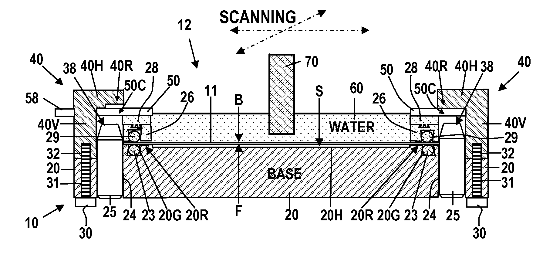
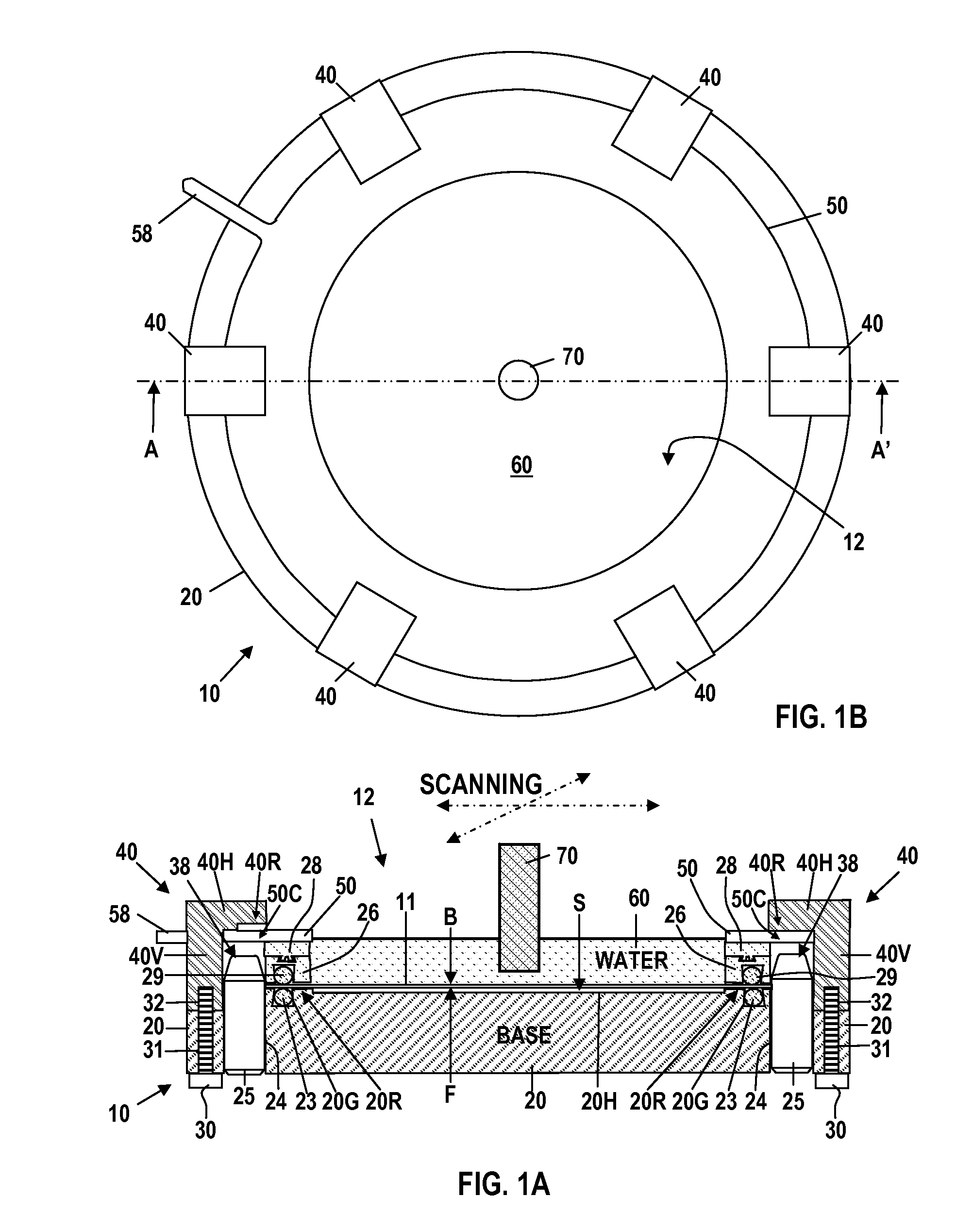
[0026]FIGS. 1A and 1B are schematic drawings of a C-SAM testing device 10 comprising a C-SAM acoustic microscope in accordance with this invention for use in testing a Device Under Test (DUT) 11 such as a silicon semiconductor wafer. FIG. 1A is an elevational sectional view of the C-SAM testing device 10 taken along line A-A′ in FIG. 1B. FIG. 1B is a plan view of the C-SAM testing device 10 of FIG. 1A. The C-SAM testing device 10 of FIG. 1A, which is used to test the integrity of features of the DUT 11, is supported by a fixture base 20.

[0027]As shown in FIG. 1A, the C-SAM testing device 10 includes a barrier structure comprising components which form a dam 12 adapted to hold a pool of acoustic transmission fluid 60 (such as water) on the planar, back surface B of the DUT 11, i.e. a silicon semiconductor wafer, thus enabling a C-SAM measurement of the type described in the copending Lu patent application, with a minimum amount of water and minimum associated setup and cleanup time. ...


PUM

PropertyMeasurementUnit
sizesaaaaaaaaaa
sizesaaaaaaaaaa
acoustic frequencyaaaaaaaaaa

Abstract

Apparatus for Scanning Acoustic Microscopy (SAM) of a semiconductor device including a substrate with an acoustic probe, The substrate has upper and lower surfaces. A sealed lower space provides an environment surrounding the lower surface. An upper ring structure formed above the upper surface includes an upper sealing ring in contact with the upper surface, with the upper sealing structure and the seal forming a dam for retaining the acoustic transmission fluid above the upper surface. A fixture base retains a lower sealing ring in contact with the lower surface surrounding the lower surface. An acoustic scanning probe positioned confronting the upper surface of the semiconductor device extending into the acoustic transmission fluid retained in contact with the upper surface.

Description

CROSS-REFERENCE TO RELATED APPLICATION[0001]This application contains subject matter which is related to the subject matter of the copending, commonly assigned U.S. patent application Ser. No. 11 / 495,243 of Minhua Lu entitled “Imaging Thin Film Structures by Scanning Acoustic Microscopy” (IBM Docket No. YOR920060306US1), which is assigned to the same assignee as this application, International Business Machines Corporation of Armonk, N.Y. The subject matter of the above patent application is hereby incorporated herein by reference in its entirety.BACKGROUND OF THE INVENTION[0002]This invention relates to fixtures employed in testing features on a first surface of a device under test, which has an opposite surface; and more particularly to means for isolating the opposite surface of a semiconductor device under test from fluids retained in contact with the first surface.[0003]In the past, measurement of features of Devices Under Test (DUT)s by Scanning Acoustic Microscopy (SAM) and C...

Claims


Application Information

Patent Timeline
Patent Type & Authority Applications(United States)
IPC IPC(8): G01N29/28G01N29/04
CPCG01N29/069G01N2291/2697G01N29/28
Inventor BAAN, ROBERT L.BAILEY, CARLA A.JAMBRIH, VLADIMIRKATZ, ROBERT P.
Owner GLOBALFOUNDRIES INC
Why Eureka
Try Eureka