Bone material removal device and a method for use thereof

a bone material and removal device technology, applied in the field of bone removal devices, can solve the problems of difficulty in removal, wear and malfunction of such tools, and difficulty in removing, so as to reduce bending moments, prevent rubbing of carving parts, and increase the rigidity of the member

Active Publication Date: 2019-10-22
T MEDICAL DEVICES AGRI COOP
View PDF94 Cites 6 Cited by
  • Summary
  • Abstract
  • Description
  • Claims
  • Application Information

AI Technical Summary

Benefits of technology

[0016]According to an aspect of some embodiments of the present invention there is provided a bone material removal device having a carving portion that also comprises a radially positioned curved plain bordered at one side thereof by the first carving edge and forming an end relief or clearance curve that prevents the rubbing of the carving portions against the bone.
[0061]According to an aspect of some embodiments of the present invention there is provided a bone material removal device, wherein axial movement of an elastic member in respect to a cannula shortens the distance between a first shaft capture point and the second shaft capture point, increasing the rigidity of a bone widening element and bringing the carving portion to be translated radially.
[0070]According to an aspect of some embodiments of the present invention there is provided a bone material removal device, wherein a carving portion comprises a radially positioned curved plain bordered at one side thereof by the first carving edge and forming an end relief or clearance curve that prevents the rubbing of the carving portions against the bone.
[0071]According to an aspect of some embodiments of the present invention there is provided a method for removal of bone material from bone, comprising drilling a bore in the bone, introducing a single elastic member including a bore widening element having a carving portion and a tip through a cannula into the bore and stressing the member to conform to the diameter of the bore, reducing the distance between a shaft capture point on the member and the tip bringing about a reduction of a bending moment acting upon the carving portion and increasing the rigidity of the member, bringing about radially directed force on the carving portion urging it to extend radially to an extended position and carving bone from walls of a bore and creating an undercut in the bone.
[0072]According to an aspect of some embodiments of the present invention there is provided a method for removal of bone material from bone, comprising drilling a bore in the bone, introducing a single elastic member including a bore widening element having a carving portion and a tip through a cannula into the bore stressing the member to conform to the diameter of the bore, reducing the distance between a shaft capture point on the member and the tip relieving the stress on the member, allowing the member to return to a resting state bringing about radially directed force on the carving portion urging it to extend radially to an extended position and carving bone from walls of a bore and creating an undercut in the bone.
[0084]According to an aspect of some embodiments of the present invention there is provided a bone material removal device, wherein a carving portion also comprises a radially positioned curved surface bordered at one side thereof by the first carving edge and forming an end relief or clearance curve that prevents the rubbing of the carving portions against the bone.

Problems solved by technology

Such techniques utilize high friction between the blade and bone not only requiring an effort to operate but may also produce debris mainly consisting of small particles that may interfere with anchor placement and removal of which may be challenging.
Various drilling tools employed to produce undercuts along bores drilled in bone rely on moveable components such as hinges, springs and similar to operate that may be expensive to manufacture and may tend to wear down and malfunction over time.
Operation of such tools may also be somewhat cumbersome to handle and require several operational steps to function.

Method used


Image

  • Bone material removal device and a method for use thereof
  • Bone material removal device and a method for use thereof
  • Bone material removal device and a method for use thereof

Examples


Embodiment Construction

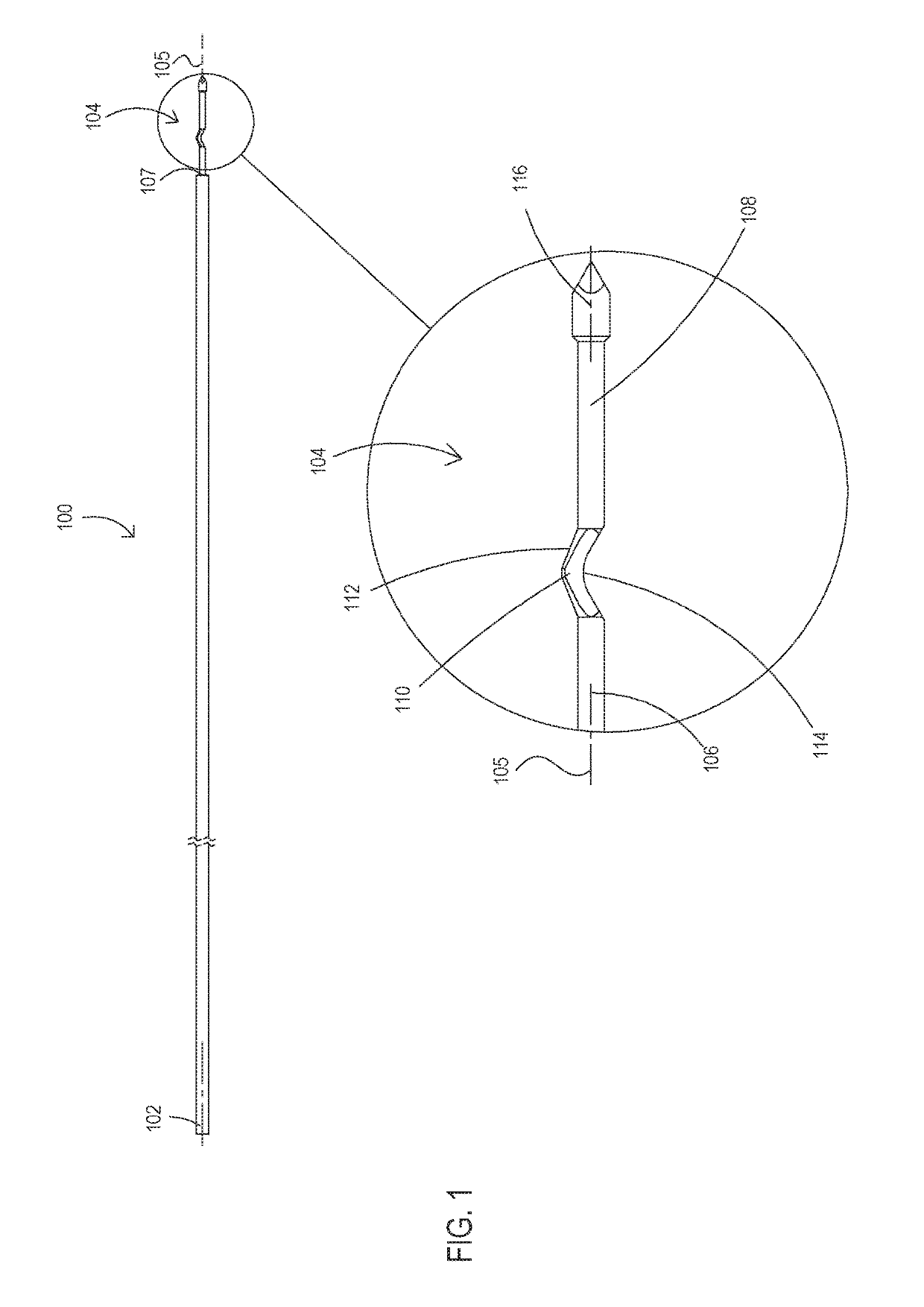
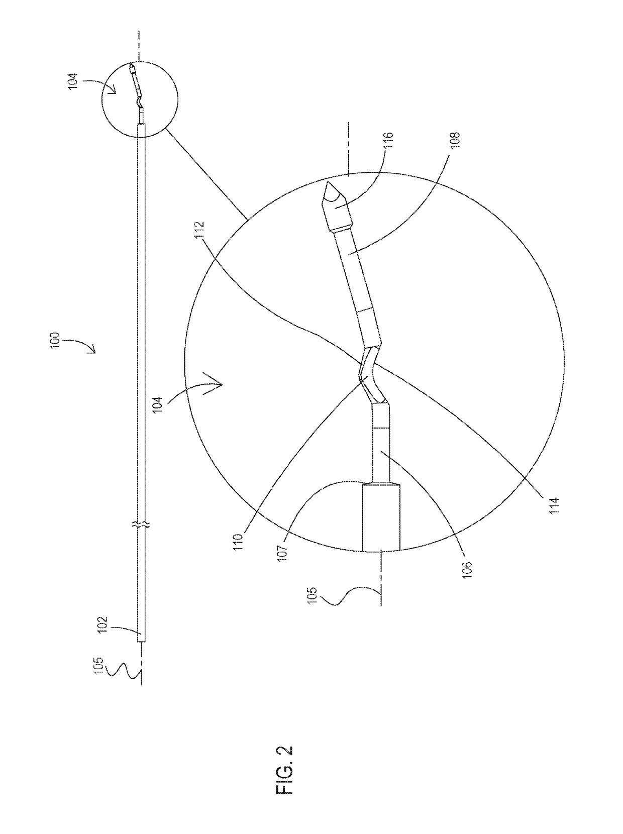
[0132]The term “bone material removal device” as used in this disclosure should be taken to mean a device that separates a portion of bone material in any form from a bone regardless of whether the separated material is cleared away from the bone or not.

[0133]The term “carving edge” as used in this disclosure should be taken to mean an edge of a portion of the bone material removal device operative to separate a portion of bone material, in any form, from a bone.

[0134]The term “carving portion” as used in this disclosure should be taken to mean a portion of the bone material removal device including a carving edge.

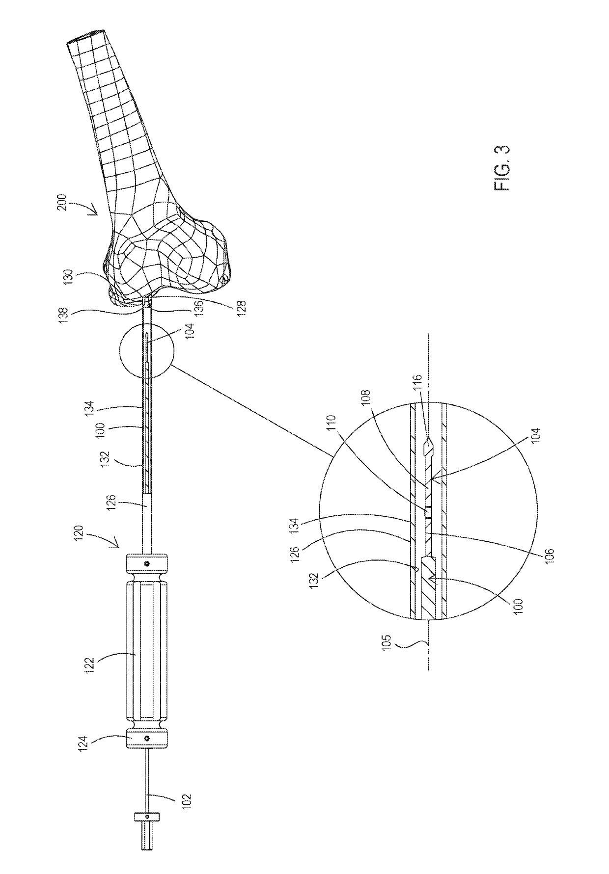
[0135]The term “shaft capture” and “shaft capture point” are used interchangeably in this disclosure and mean a point of contact between a shaft and a surrounding surface that temporarily limits radial movement of the shaft at that location.

[0136]A bone material removal device is disclosed herein, which is particularly useful for drilling a small diameter bore having one o...


PUM


Abstract

A bone material removal device including a cannula, a bone drilling forward tip and a bore widening element including a bone carving portion that slides axially relative to the cannula and extends in a circumferential direction and wherein the axial movement of the bore widening element relative to the cannula brings a carving portions to travel and extend radially in a circumferential direction beyond a surface of the cannula and carve bone from a wall of a bore.

Description

RELATED APPLICATIONS[0001]This application is a National Phase of PCT Patent Application No. PCT / IL2016 / 050370 having International filing date of Apr. 7, 2016, which claims the benefit of priority under 35 USC § 119(e) of U.S. Provisional Patent Application Nos. 62 / 144,991 file on Apr. 9, 2015 and 62 / 151,375 file on Apr. 22, 2015. The contents of the above applications are all incorporated by reference as if fully set forth herein in their entirety.FIELD OF THE INVENTION[0002]The present invention, in some embodiments thereof, relates to bone removal devices, and more particularly, but not exclusively, to devices that change effective diameter of bores.BACKGROUND OF THE INVENTION[0003]Various orthopedic reconstructive procedures and particularly ligament or tendon reconstructive procedures such as, for example, Anterior Cruciate Ligament (ACL) reconstruction require, implantation of a surgical tissue graft (e.g., ligament graft) inserted into the bone in order to replace the injure...

Claims


Application Information

Patent Timeline
Patent Type & Authority Patents(United States)
IPC IPC(8): A61B17/16
CPCA61B17/1617A61B17/1635A61B17/1675A61B17/1642A61B17/1631A61B17/1633
Inventor SLOBITKER, LEONSITRY, HAGAYKOTOV, ALEXANDERWEISMAN, RAN
Owner T MEDICAL DEVICES AGRI COOP
Why Eureka
Try Eureka