Dairy milking devices and methods

a milking device and a technology for dairy products, applied in the field of dairy milking devices and methods, can solve the problems of difficult to handle all four liners in this fashion, and achieve the effects of improving the milking cluster, improving the alignment of the cluster, and being convenient to handl

Active Publication Date: 2014-07-10
LAUREN AGRISYST
View PDF11 Cites 6 Cited by
  • Summary
  • Abstract
  • Description
  • Claims
  • Application Information

AI Technical Summary

Benefits of technology

[0009]The configurations of this disclosure are designed to improve the milking cluster in several different ways: improved alignment of the cluster during milking, making the cluster easier to handle (attaching to cow, placing in wash position, etc.), reducing the likelihood of the cluster interfering with the cow during milking, and reducing the likelihood of the cluster being stepped on or caught in the cows hoof or leg.
[0010]The disclosure provides configurations wherein the “bowing” outwardly of the short air tubes is eliminated when the cluster is in the milking position. In one configuration the bowing is reduced or eliminating by aligning the pulsation nipples with the liner nipples such that the centerlines of each are spaced apart but generally parallel. One exemplary configuration is provided wherein the pulsation nipples and air fork are integrated with the claw. Another configuration is provided wherein the air fork is separate from the claw but positions it pulsation nipples at the ends of arms such that the pulsation nipples are aligned with the liner nipples when the air fork is disposed on top of a claw. Eliminating the bowing of the short air tubes gives the cluster a more uniform alignment under the cow and decreases the likelihood of the short air tube interfering with the cow's legs while milking. It also provides for a sleeker easier to handle cluster assembly which is advantageous to milkers during attaching and handling. The design decreases the “footprint” of the cluster which helps with a number of other things, namely: getting caught in the cow's hoof / leg when detaching, less likely to bother the cow therefore less likely to get kicked off—both of these could lead to less cuts in the short air tube.
[0011]Proper cluster alignment is desirable. Clusters should hang as evenly under the udder as the shape of the udder allows. By eliminating the outwardly bowing short air tubes, the disclosed configurations provide a more compact design thus making it easier to hang the cluster properly and adjust it after it has been hung. The disclosed configurations reduce the likelihood that the short air tube will come into contact with the cow's leg is known to push the unit out of its natural hanging position.
[0012]The disclosure also provides an integrated short milk tube and short air tube. By eliminating the detached short air tube, the unit becomes easier to handle and prevents the gap from forming between the two tubes. The integrated configuration has uniform ends that engage the nipples of the air fork and claw side-by-side. This is an advantage as speed in the parlor desirable. On many dairy operations, the milkers grab the two liners on the left side with one hand and the two liners on the right side with the other hand. They simultaneously attach the front two teats with a liner from each hand and then the back teats the same way. The traditional short air tube makes it difficult to handle all four liners in this fashion as the air tubes pull the liners in a direction different from the short milk tube. When grabbing the traditional short air tube the liner and short air tube are bending on multiple axes at different planes to get to the milking position. The disclosed configurations provide tubes that direct force to the milking liner in a consistent manner which helps the milker attach pairs of liners at the same time.
[0015]The disclosure provides a visual location feature that helps align the liner with the shell.

Problems solved by technology

The traditional short air tube makes it difficult to handle all four liners in this fashion as the air tubes pull the liners in a direction different from the short milk tube.

Method used


Image

  • Dairy milking devices and methods
  • Dairy milking devices and methods
  • Dairy milking devices and methods

Examples


Embodiment Construction

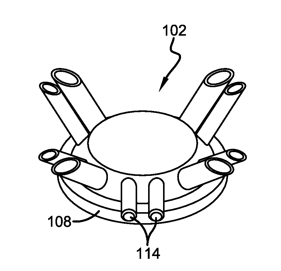
[0060]An exemplary configuration of a claw top with an integrated air fork is indicated generally by the numeral 102 in FIGS. 5-8. Claw top 102 may be fabricated from a variety of materials such as metals and plastics. Claw top 102 may be removably connected to or integrally formed with any of a variety of claw bodies. Claw top 102 includes a plurality of liner nipples 104 and a corresponding number of pulsation nipples 106. Each pair of nipples 104 and 106 that are next to each other and configured to work with a single milking liner and shell combination is a nipple pair. Claw top 102 of FIG. 5 has four nipple pairs. Each liner nipple 104 is configured to be connected with the lower end of a short milk tube and each pulsation nipple 106 is configured to be connected with the lower end of a short air tube. Each nipple 104 and 106 extends away from the upper wall 108 of claw top 102 at an extension direction. The extension direction of each nipple of a nipple pair is substantially t...


PUM


Abstract

A milking liner includes an integrated short air tube and short milk tube. In one configuration, the pulsation air is delivered through the bead of the milking liner directly inside the shell through a plurality of outlets. The disclosure also provides alignment features that assist the person assembling a milking liner and shell. The features limit rotation between the liner and the shell. The liner includes a short air tube that extends beyond a short milk tube with each having a sealing bead. The sealing beads are offset from each other.

Description

CROSS REFERENCE TO RELATED APPLICATIONS[0001]This application claims the benefit of U.S. Provisional Patent Application Ser. No. 61 / 734,940 filed Dec. 7, 2012; the disclosures of which are incorporated herein by reference.BACKGROUND OF THE DISCLOSURE[0002]1. Technical Field[0003]The disclosure relates to one or more of the following items individually and in combination: vacuum dairy milking machinery, both manually-connected and robotically-connected; methods for extracting milk from dairy animals, milk claws, milk claw tops, pulsation caps (air dividers or air forks) used in conjunction with milk claws, the arrangement of pulsation nipples and liner nipples, milking liners, short milk tubes, short air tubes, milking liner and shell combinations, and method of delivering pulsation air to a milking liner and shell combination.[0004]2. Background Information[0005]Dairy milking machines are well known in the art. One common form of these machines includes a claw 2 (see FIG. 1) that ty...

Claims


Application Information

Patent Timeline
Patent Type & Authority Applications(United States)
IPC IPC(8): A01J5/00
CPCA01J5/00A01J5/08A01J5/041A01J5/16A01J7/00A01J5/06
Inventor KOCHMAN, AARONPFEIFFER, CHRISTOPHER B.NIBALI, BENJAMIN D.HALL, KRISTOPHER C.MITCHELL, GARY L.
Owner LAUREN AGRISYST
Why Eureka
Try Eureka